
Physical vapour deposition (PVD) is a vacuum coating process that deposits thin, dense films on tools and components to cut wear, reduce friction, and improve corrosion resistance. Typical PVD layers are 1–5 micrometers thick with high hardness and strong adhesion. For Woodbridge manufacturers, it turns chronic tooling issues into measurable uptime and quality gains.
By Ron — Sputtek
Last updated: 2026-07-07
Overview
This practical guide explains physical vapour deposition from fundamentals to factory adoption. You’ll learn what PVD is, why it matters for uptime and quality, how it works, where it outperforms alternatives, and how to specify coatings that scale from pilots to high‑volume runs in Woodbridge and beyond.
PVD often sounds complex, but the payoff is simple: longer tool life, steadier output, and fewer line disruptions. In our experience supporting Tier‑1 and regulated sectors, the winning formula pairs correct coating chemistry with disciplined pre‑/post‑processing and repeatable equipment.
- What PVD is and how it works
- When to choose PVD vs CVD or thermal spray
- Which coatings (TiN, CrN, AlTiN, DLC) fit your failure mode
- How to specify finish, edge prep, masking, and QC
- How Sputtek supports pilots to volume with ISO 9001:2015 and Nuclear N299.3
- Quick navigation:
- What is PVD?
- Why PVD matters
- How PVD works
- Types, methods, and materials
- Best practices
- Tools and resources
- Case studies and examples
- FAQ
What Is Physical Vapour Deposition (PVD)?
Physical vapour deposition is a family of vacuum processes—chiefly cathodic arc and sputtering—that deposit hard, adherent thin films on substrates. Coatings like TiN, CrN, AlTiN, and DLC typically measure 1–5 µm, push hardness past 2,000 HV, and can lower friction near 0.1–0.2 depending on chemistry.
Engineers sometimes see both spellings—physical vapour deposition and physical vapor deposition. Standards and OEM specs in North America often use the American “vapor,” but we’ll use the search-friendly form “vapour” here. For foundational context, our own PVD coating guide expands the basic definitions with application notes.
Core properties that matter on the shop floor
- Hardness and density: High-hardness films resist abrasion and micro-chipping. Dense microstructures block diffusion and galling.
- Low friction (select chemistries): DLC and TiCN reduce adhesive wear and sticking on dies, punches, and molds.
- Thermal stability: AlTiN/AlCrN sustain edge integrity during high-SFM and dry machining where heat spikes.
- Thin, conformal coverage: 1–5 µm preserves tolerances, surface geometry, and sharp cutting edges.
Where PVD excels
- Stamping and forming: CrN and DLC curb galling on AHSS and sticky alloys.
- Cutting tools: AlTiN/AlCrN extend edge life in high-temperature duty cycles.
- Molding: DLC improves release, cleans faster, and protects polished cavities.
- Precision components: TiN/CrN add wear and corrosion resistance without dimensional penalty.
Why PVD Matters for Manufacturers
PVD improves OEE by extending tool life, reducing unplanned changeovers, and stabilizing quality. On real lines, that shows up as longer maintenance intervals, lower scrap, tighter Cp/Cpk, and more predictable scheduling—especially in high-mix or high-speed operations.
Here’s the thing: tools rarely fail for a single reason. Abrasion, adhesion, heat, and corrosion interact. PVD lets you tune chemistry to the dominant failure mode while preserving edge geometry, so you extend life without adding rework risk. We’ve seen this pattern across stamping, cutting, molding, and precision assembly.
Operational levers you can quantify
- Life extension: Thin hard films slow abrasive wear on dies, punches, and edges.
- Lower friction: DLC and TiCN reduce sticking/picking in forming and pharma tooling.
- Heat resistance: AlTiN/AlCrN keep hardness at elevated temperatures for dry or high-SFM machining.
- Corrosion defense: CrN resists moisture and some chemistries without thick build-up.
Want more context by application? Our concise PVD deposition guide outlines common use cases and failure modes engineers flag during trials.
How Physical Vapor Deposition Works
PVD loads cleaned, fixtured parts into a vacuum. A metal target is vaporized by energetic ions or an arc. With reactive gases, atoms combine to form a compound (for example, Ti + N → TiN) that condenses atom-by-atom on the surface. Surface prep and post-lapping are critical to final performance.
Although multiple variants exist, the core stages stay consistent. A stable, clean base enables adhesion. Balanced fixturing ensures even heating and line-of-sight growth. Controlled plasma and gas flows set phase and composition. Finally, post-processing tunes roughness and edges, preventing micro-cracks or premature flake-off.
- Pre-clean and activation: Degreasing, blasting or microblasting, and thermal cleaning remove residues and activate the surface.
- Masking and fixturing: Critical dimensions are masked; parts are oriented for uniform deposition and thermal mass balance.
- Evaporation/sputtering: Cathodic arc or sputter sources release metal species; reactive gas forms nitrides/carbides/carbon films.
- Growth and densification: Temperature, bias, and pressure shape grain, density, and stress for adhesion and toughness.
- Post-processing: Lapping/polishing and QC verification (thickness, adhesion, roughness) lock in repeatability.
Arc vs sputter vs e‑beam (where it fits)
- Cathodic arc: High energy, good adhesion; macroparticle filtering is key for smooth finishes.
- Magnetron sputter: Excellent for smooth, low‑defect films and multilayers; widely used for CrN, DLC variants.
- Electron‑beam PVD: Useful in niche, high-rate evaporation; more common in optics/aero thermal barriers.
Types, Methods, and Coating Choices
Choose coating chemistry by failure mode and duty cycle. TiN is a generalist; TiCN lowers friction; CrN curbs galling and moisture attack; AlTiN/AlCrN carry hot hardness for aggressive machining; DLC delivers ultra‑low friction for forming, pharma, food tooling, and select components.
Common PVD materials
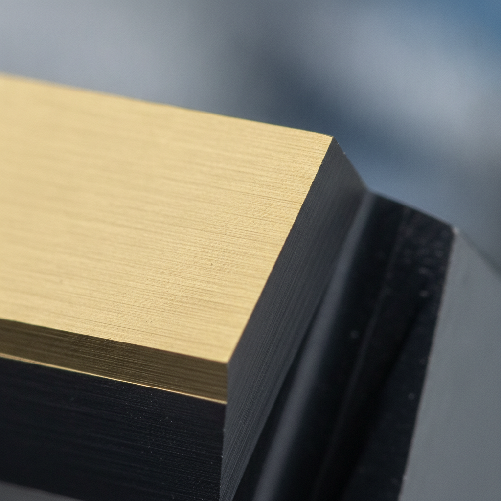
- TiN (titanium nitride): Visible gold hue; broad wear resistance; easy inspection.
- TiCN (titanium carbonitride): Higher hardness than TiN; lower friction for sliding contact.
- CrN (chromium nitride): Great against adhesive wear and humidity; popular on dies and molds.
- AlTiN / AlCrN: Superior hot hardness; ideal for high-SFM or dry machining.
- DLC (diamond-like carbon): Extremely low friction; biocompatibility advantages for medical/pharma and good release in molding.
Applications we see most often
- Stamping: CrN or DLC on trim dies and draw beads to fight galling on AHSS and aluminum.
- Cutting and machining: AlTiN/AlCrN on carbide end mills, drills, and inserts for heat management.
- Plastic injection molds: DLC on core pins, gates, and polished cavities to speed release and cleaning.
- Pharma and food tooling: DLC on punches and tooling surfaces to reduce sticking and friction.
- Precision components: TiN/CrN where dimensions are tight but surfaces see sliding or wear.
Substrate compatibility notes
- Carbide and HSS: Excellent candidates for high-hardness duty cycles.
- Tool steels (D2, H13, etc.): Match heat treatment to expected service temperature under coating.
- Stainless and non-ferrous: Use CrN/DLC for corrosion and release; control pre-clean for passivated surfaces.
- Polymers and hybrids: Consider thermal limits and bonding layers; basic polymer behavior differences are summarized in this thermoplastic vs thermoset overview.
PVD vs Alternatives: Quick Comparison
Use PVD for thin, hard, low‑friction films at moderate temperatures. Choose CVD when higher temperatures and conformality are acceptable. Pick thermal spray (including HVOF/thermospray) for thick erosion/corrosion barriers or dimensional restoration measured in tens to hundreds of micrometers.
| Method | Typical Temp | Thickness | Strengths | Typical Uses |
|---|---|---|---|---|
| PVD | 150–500°C | 1–5 µm | Hard, low friction; preserves dimensions | Stamping, cutting, molds, precision parts |
| CVD | >700°C | 2–10 µm | Excellent conformality; strong diffusion bonds | High-temp tooling, complex shapes |
| Thermal spray (HVOF/Thermospray) | Substrate stays cooler | 50–300+ µm | Thick, corrosion/erosion barriers; restore dimensions | Pumps, valves, shafts, wear sleeves |
Need a deeper dive on options? Our overview of physical vapor deposition companies explains how providers position thin films versus thick-film spray solutions in mixed fleets.
Best Practices for Specifying PVD
Write specs around the failure mode, not the brand name. Define substrate and heat treat, target surface finish, edge prep, masking zones, and cleanliness. Pilot on a small tool set, verify thickness/adhesion, measure life and quality, then lock the recipe before scaling.
Checklist engineers actually use
- Clarify the failure mode: Abrasion, adhesion (sticking/picking), heat softening, or corrosion?
- Match coating to mode: CrN/DLC for galling; AlTiN/AlCrN for hot edges; TiCN for sliding contact.
- Specify the surface: Pre-coat roughness (Ra/Rz), edge prep, and any polishing/lapping after coating.
- Masking and fits: Call out datums, threads, bores; avoid stack-up on tight tolerances.
- Measurement plan: Thickness (target and tolerance), adhesion qualitative test, roughness before/after.
- Pilot protocol: Baseline tool life, scrap, cycle time; run coated tools side-by-side under real takt.
Process control signals to look for
- Pre-/post in-house: Sandblasting, microblasting, stripping, and lapping under one roof reduce variation.
- Quality credentials: ISO 9001:2015 is table stakes; for nuclear, N299.3 approval shows added rigor.
- Run capacity: Large-batch systems stabilize recipes across shifts and product families.
- Documentation: Work instructions, traveler records, and QC reports create repeatability.
Request a coating assessment
Not sure which chemistry to start with? Share your failure mode and duty cycle. We’ll recommend a pilot plan and a verification checklist you can reuse for future change control. Start the conversation at sputtek.com.
Tools, Equipment, and Resources (Sputtek)
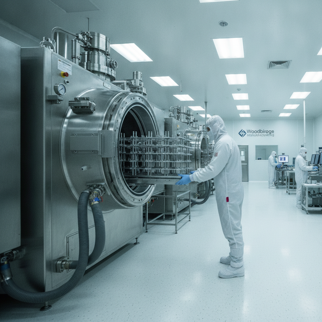
Sputtek operates multiple PVD systems and a Thermospray cell in its modern Greater Toronto facility, with end-to-end pre‑/post‑processing and a QC lab. High-capacity SPUN systems support stable large-batch runs, while ISO 9001:2015 and Nuclear N299.3 approvals underpin regulated work.
- High-capacity PVD systems: SPUN 2,000 (up to 1,200 kg/cycle) and SPUN 4,000 (up to 3,000 kg/cycle) for large families and even loading.
- Thermospray (including Pulsed HVOF): Thick protective layers where erosion/corrosion or dimensional restoration dominates.
- In-house pre-/post: Sandblasting, microblasting, degreasing, stripping, polishing, after-coat lapping.
- QC laboratory: Thickness, roughness, adhesion checks; documentation tailored to your PPAP or validation needs.
- Engineering support: Prototype-to-production transfer with recipe control and continuous improvement.
If you need a deeper primer before kicking off a pilot, this materials purity explainer offers a useful reminder: upstream cleanliness drives downstream repeatability—a principle that holds for coatings as well.
Case Studies and Practical Examples
The fastest path to confidence is a measured pilot. Start with one tool family, collect baseline life and quality, then introduce PVD and monitor deltas over two or three cycles. Most teams graduate to standard recipes after seeing stable improvements.
Automotive stamping (AHSS trim and draw)
- Problem: Adhesive wear and galling caused frequent die cleaning and edge rework.
- Approach: CrN on critical contact surfaces; polish and lap post‑coat to a target Ra that maintained draw performance.
- Result: Longer clean intervals and steadier part finish; maintenance could plan instead of react.
Injection molding (core pins and gates)
- Problem: Sticking increased cycle time and required aggressive solvents for cleanup.
- Approach: DLC with controlled thickness to preserve geometry; verified release on a short-run trial first.
- Result: Faster release and less residue; cleaning moved from urgent to scheduled.
Carbide end mills (dry machining)
- Problem: Edge softening at high SFM led to rapid tool changeovers.
- Approach: AlTiN tuned for heat resistance; ensured pre-coat edge prep was consistent across batches.
- Result: More predictable edge retention at temperature; changeovers aligned with planned stops.
Pharma tablet tooling
- Problem: Picking and sticking compromised tablet imprint fidelity.
- Approach: DLC with strict surface finish control and documented traceability.
- Result: Smoother ejection and more consistent imprints under validated procedures.
For a broader industry lens on modernization and sustainability in metals manufacturing, see this innovation profile as an external example of continuous improvement thinking.
Working with a Local PVD Partner in Woodbridge
Local support reduces logistics friction, shortens pilot loops, and speeds troubleshooting. For Woodbridge teams, proximity to a certified PVD provider means faster turnarounds on urgent trials and closer collaboration between manufacturing engineering and coating process engineers.
When we work with manufacturers around Woodbridge, hands-on collaboration shortens the learning curve. Quick in-person reviews of failed tools or sample runs let both teams align on root causes and dial in recipes quickly—especially helpful in high-mix plants or regulated programs.
Local considerations for Woodbridge
- Plan deliveries around SmartCentres Woodbridge peak retail hours to keep logistics punctual.
- Seasonal humidity swings can influence pre-clean consistency; align schedules so pretreatment remains stable in winter.
- For fast team access and drop‑offs, coordinate near Weston Rd / Highway 7 transit corridors.
If you’re mapping a first pilot, our PVD coating guide includes a one-page pilot template you can adapt to your line.
Implementation Plan: From Pilot to Standard Recipe
Start small, measure tightly, then scale. Define a pilot scope, collect baselines, coat a subset, monitor results, and document the final recipe with QC checkpoints. Once stable, roll it into standard work and approved supplier lists.
- Pick a family: Choose tools with clear failure modes and reliable baseline data.
- Capture baselines: Life, scrap, cycle time, cleaning frequency, surface finish, and changeovers.
- Run a coated subset: Keep other variables the same; track for two or three cycles.
- Review and lock: If gains are stable, freeze thickness, finish, and post‑processing in your spec.
- Scale smart: Expand to similar tools; update work instructions and preventive maintenance.
For background on polymer behavior that sometimes intersects with hybrid assemblies, this short primer on thermoplastics versus thermosets is a handy refresher when fixtures or components include engineered plastics.
Physical Vapour Deposition FAQ
These quick answers address the most common engineering and quality questions about physical vapour deposition. Each response is concise and direct so teams can move from research to action without delay.
What thickness should I specify for PVD?
Most applications run 1–5 µm. Thinner layers preserve sharp edges on cutting tools; slightly thicker films can help on sliding or abrasive surfaces. Tie thickness to failure mode, then verify with cross-sections or calibrated measurements during the pilot.
How do I prepare parts for PVD?
Start with thorough degreasing and controlled blasting or microblasting to activate the surface. Define masking on threads, bores, or datums. Ensure stable fixturing for uniform heating and line-of-sight coverage. After coating, confirm roughness and adhesion before release.
Is DLC safe for medical or food tooling?
DLC is widely used where low friction and smooth release are essential, including medical and pharmaceutical tooling. Confirm coating chemistry, cleanliness, and traceability meet your quality system and regulatory expectations before approval.
When is thermal spray better than PVD?
Choose thermal spray (including HVOF/Thermospray) for thick protective layers or dimensional restoration in the 50–300+ µm range. It excels for erosion and corrosion, while PVD focuses on thin, hard, low‑friction films that preserve tight dimensions.
What’s the fastest way to prove value?
Run a small pilot with clear baselines. Track life, scrap, cycle time, and cleaning frequency. If the coated subset shows stable improvement over two to three cycles, freeze the recipe and implement it as standard work for similar tools.
Key Takeaways
Physical vapour deposition extends tool life and stabilizes quality without adding dimensional risk. Focus on failure modes, specify finish and thickness, pilot quickly, and scale only after you verify repeatable gains under real takt.
- PVD is thin (1–5 µm), hard, and low friction for the right chemistries.
- Match coating to failure mode: abrasion, adhesion, heat, or corrosion.
- Surface prep and post‑processing drive adhesion and performance.
- Pilot with data; lock the recipe before scaling to volume.
- Local support in Woodbridge shortens loops and speeds decisions.
Conclusion
The smart path to PVD is purposeful and measured: diagnose the failure mode, select chemistry, control the surface, and verify the results. With that discipline, PVD becomes a durable lever for uptime, quality, and maintenance predictability.
Ready to translate physical vapour deposition from theory to throughput? Start a quick pilot in Woodbridge, validate the gains, then standardize across similar tools. If you’d like help mapping the steps, our engineering team can review your parts, propose a recipe, and outline a verification plan at sputtek.com.