
Last updated: October 2026
By Ron – Sputtek
Physical vapour deposition PVD is used when a surface needs more performance than the underlying material can provide on its own. A steel forming die may need better resistance to galling, a carbide cutter may need improved hot-wear performance, or a molding component may need lower friction during repeated sliding. Instead of making the entire component from a more expensive or less workable material, PVD adds a functional surface layer.
This guide explains what PVD does, how the process is controlled, how common films differ, and what an engineering team should include in a coating specification. It also covers PVD coating services for manufacturers in Woodbridge and the surrounding Greater Toronto Area, where preparation, fixturing, process control, and logistics can affect the success of a production program.
What Is Physical Vapour Deposition PVD?
Physical vapour deposition is a family of vacuum coating processes in which material from a solid source is converted into a vapour or highly energetic flux and deposited as a thin film on a prepared component. Depending on the equipment and target material, the process may use cathodic arc evaporation, magnetron sputtering, or related plasma-assisted techniques.
During deposition, the coating material reacts with process gases such as nitrogen or carbon-containing gases, or is deposited in a controlled elemental form. The resulting film may be a nitride, carbide, carbon-based coating, multilayer, or another engineered thin-film structure. The part remains a separate substrate: PVD changes the working surface without replacing the bulk material.
The American spelling is “physical vapor deposition.” In Canada and Ontario, “physical vapour deposition” is also current terminology. The abbreviation PVD refers to the same coating family in both forms.
What PVD changes at the surface
A PVD film can change several surface properties at once. Hardness can improve resistance to abrasive wear, while a lower-friction surface can reduce sliding losses, built-up edge, or release problems. Some chemistries also provide useful resistance to oxidation, corrosion, adhesive wear, or chemical interaction with the working material.
PVD is normally selected for a thin functional layer rather than a thick dimensional build-up. Production coating thickness is often specified in the low-micron range, with the final value determined by the coating system, substrate, geometry, and application. Because the layer is thin, fits and edge geometry can often be retained more easily than with a thick overlay, but masking and tolerance planning are still essential.
What PVD does not solve by itself
A coating cannot compensate for a cracked substrate, poor heat treatment, severe misalignment, inadequate lubrication, or contamination before deposition. It also cannot make every geometry coat uniformly: PVD is substantially influenced by line-of-sight access, fixture rotation, shadowing, and the location of edges and recesses.
For that reason, coating selection should begin with the failure mode rather than with colour or hardness alone. Ask whether the dominant problem is abrasion, adhesion, friction, corrosion, heat, fatigue, or a combination. That diagnosis determines which film and process window deserve evaluation.
Why Manufacturers Use PVD Coatings
PVD coating services are most valuable when surface wear or friction is limiting production performance. A suitable film can help a tool hold its profile longer, reduce material transfer, improve release, or make a component more stable during repeated cycles. The business benefit is usually indirect: fewer interventions, more consistent parts, and a clearer maintenance plan.
Wear and edge retention
A hard film can protect a cutting edge, forming surface, punch, or mold feature from abrasive contact. This is particularly relevant when the working material contains hard particles, such as glass-filled polymers, or when a tool experiences repeated contact with sheet, powder, or chips. The substrate still carries the structural load, while the film protects the exposed surface.
Lower friction and improved release
Low-friction coatings can reduce sliding resistance in guides, lifters, ejectors, seals, and other moving interfaces. In molding, a suitable carbon-based or nitride coating may help reduce sticking and ejector marks. In machining, friction control can support chip evacuation and reduce the tendency of material to adhere to the tool.
Resistance to adhesive wear and galling
Galling occurs when contacting materials transfer, weld locally, and tear the surface during sliding. Forming tools working with galvanized or other difficult sheet materials are common candidates for coatings selected to reduce adhesive interaction. The coating is only one part of the solution; clearance, surface finish, lubrication, alignment, and forming conditions also need review.
More stable production conditions
When a tool wears gradually, dimensions and surface quality can drift before the problem becomes obvious. A coating may slow that change and make inspection or replacement intervals more predictable. Engineering teams should confirm the effect with their own measurements, such as tool life, part dimensions, surface defects, cleaning frequency, or maintenance events, rather than assuming a universal improvement.
Woodbridge manufacturing considerations
For a manufacturer operating in Woodbridge, Ontario, local coordination can make pilot work easier. Parts can be reviewed, prepared, coated, inspected, and returned without treating every trial as a long-distance logistics project. The practical benefit is faster feedback when a fixture, mask, edge preparation, or coating chemistry needs adjustment.
Production planning should still allow time for cleaning, inspection, fixturing, deposition, post-processing, and quality release. A coating campaign scheduled immediately before a shutdown or launch may create avoidable risk if the specification has not been proven on representative parts.
How the PVD Process Works
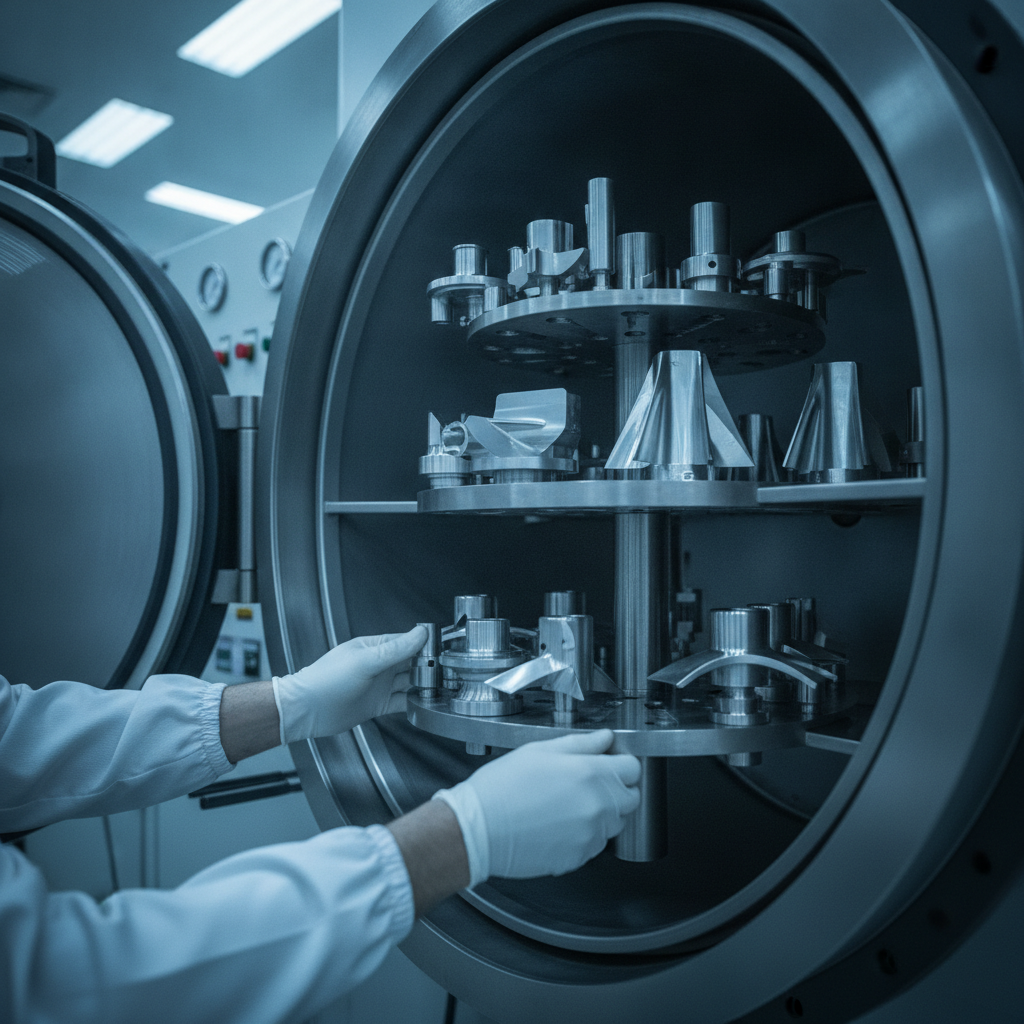
A reliable PVD result is a chain of controlled operations rather than a single chamber cycle. Surface preparation, part history, fixturing, heating, plasma cleaning, deposition, cooling, finishing, and inspection all influence adhesion and uniformity. A coating supplier should be able to explain how those stages are controlled for the specific part.
1. Review the substrate and failure mode
The process begins with the base material, heat treatment, dimensions, surface finish, and intended service. The supplier needs to know whether the part is tool steel, stainless steel, carbide, or another compatible material, and whether it can tolerate the planned thermal exposure. Existing cracks, burrs, decarburized areas, damaged edges, or embedded contamination should be addressed before coating.
2. Clean and prepare the surface
Oil, coolant, polishing compound, fingerprints, oxides, and other residues can interfere with nucleation and adhesion. Cleaning may include aqueous degreasing, rinsing, drying, solvent steps, and controlled blasting or polishing appropriate to the substrate. Preparation must remove contamination without rounding a functional edge or changing a critical surface beyond its drawing requirement.
3. Fixture and mask the parts
Most PVD deposition has a directional component. Fixtures therefore determine which surfaces receive direct flux and how uniform the film will be around edges, bores, recesses, and opposing faces. Parts may be rotated or moved during the cycle, while masks protect gage points, threads, fits, or areas that must remain uncoated.
4. Establish vacuum and plasma conditions
The chamber is evacuated to reduce unwanted gas and contamination. Plasma cleaning or ion etching can then activate the substrate and remove remaining surface films immediately before deposition. Pressure, bias, gas composition, target power, and substrate temperature are controlled according to the selected coating system.
5. Deposit the coating
In cathodic arc evaporation, an arc releases highly ionized material from a solid target. In magnetron sputtering, energetic ions dislodge atoms from a target and those atoms travel toward the parts. HiPIMS and other process variants can provide additional control over ionization and film density. Reactive gases allow compounds such as nitrides to form during deposition.
6. Cool, unload, and finish
Controlled cooling helps manage residual stress and protects the substrate. Depending on the application, light polishing or lapping may be used to restore edge sharpness, achieve a specified roughness, or remove unwanted surface texture. The finishing step should be defined before coating because it can influence the final film and functional geometry.
7. Inspect and release the batch
Inspection may include visual examination, thickness measurement, surface roughness, adhesion testing, hardness or microstructure checks, and dimensional verification. The appropriate method depends on the part and specification. Representative coupons can provide useful process evidence, but critical production features may need direct measurement as well.
How to Choose a PVD Coating
No single PVD coating is best for every application. The selection should connect the failure mode to the contact conditions: load, speed, temperature, lubrication, counterface, abrasive particles, chemical exposure, and required geometry. Colour can help identify a coating, but it is not a substitute for a performance specification.
| Coating family | Often considered for | Selection questions |
|---|---|---|
| TiN | General wear resistance, cutting and forming tools, visual identification | Is general abrasive or adhesive wear the primary issue? Is the operating temperature appropriate? |
| CrN | Forming, molding, corrosion-related service, adhesion and galling concerns | Will the surface contact galvanized sheet, moisture, or a chemically active environment? |
| AlTiN or TiAlN | Cutting tools and applications involving elevated cutting temperatures | Will the tool generate enough heat for the coating’s hot-wear behaviour to be useful? |
| DLC | Sliding, start-stop, fretting, poor lubrication, and release applications | Is friction the dominant failure mode, and is the substrate and counterface compatible? |
| Multilayer or nanolayer systems | Applications needing a balance of toughness, hardness, and crack resistance | Does the added architecture address a demonstrated failure mode? |
TiN for general-purpose wear
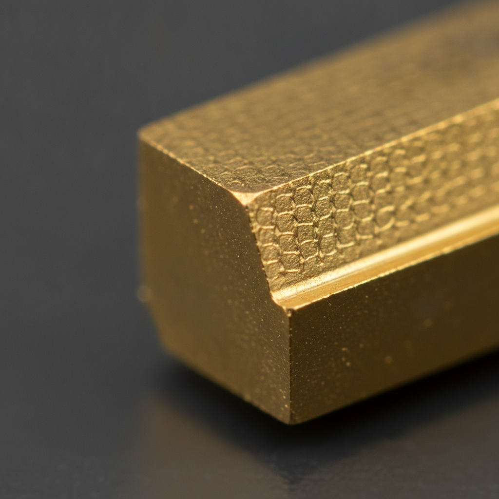
TiN is widely recognized by its gold appearance and is used on many cutting, forming, and tooling applications. It can be a sensible starting point when abrasive wear or general surface protection is the main concern. The final choice should still consider the substrate, temperature, chip load, lubrication, and required edge preparation.
CrN for forming and corrosion-related duty
CrN is often evaluated where toughness, corrosion resistance, and reduced material transfer matter. It may suit forming tools that work with difficult sheet materials or components exposed to moisture and mixed service conditions. Coating thickness and post-coating finish should be selected with the tool’s clearances and surface requirements in mind.
AlTiN and TiAlN for hot cutting conditions
AlTiN and TiAlN systems are commonly considered for cutting tools exposed to elevated temperatures. Their value depends on the cutting strategy and whether the operating conditions allow the coating to develop its intended thermal performance. A change in coating does not replace correct speed, feed, coolant, edge preparation, and tool geometry.
DLC when friction dominates
DLC describes a family of diamond-like carbon films rather than one universal recipe. DLC may be considered for sliding interfaces, ejectors, lifters, seals, and components that experience start-stop or limited lubrication. The supplier should confirm compatibility with the substrate, counterface, load, temperature, and any fluids or polymers involved.
When a multilayer is justified
Multilayer and nanolayer designs alternate materials or compositions to combine properties that are difficult to achieve in a single layer. They may help manage crack propagation, wear, or changing service conditions. They should be selected because testing or application experience identifies a need, not simply because a more complex stack sounds better.
Designing, Preparing, and Qualifying PVD Parts
Good coating outcomes are often determined before the part enters the chamber. A drawing or purchase order should communicate the surfaces to be coated, the target film, allowable thickness, finish, masking, substrate condition, and acceptance tests. Ambiguous requirements can produce a technically acceptable film that still fails the application.
Include useful drawing callouts
- Substrate material and heat-treatment condition.
- Coating family or approved coating designation.
- Nominal thickness and allowable range.
- Surfaces to coat, mask, or inspect.
- Pre-coating and post-coating roughness requirements.
- Critical dimensions, fits, edges, and gage points.
- Required adhesion, thickness, visual, and dimensional checks.
Where a coating supplier recommends a different range after a pilot, revise the controlled specification rather than relying on an informal email. The coating callout should appear in the drawing, purchase order, traveller, or control plan used by the people releasing the part.
Manage tolerances and geometry
A low-micron film can still matter on a close running fit, sharp cutting edge, seal land, or small bore. Masking may be required, and the fixture may need to expose specific faces consistently. Deep cavities and surfaces hidden behind shoulders deserve an early review because line-of-sight limitations may create non-uniform thickness.
Set a realistic thermal budget
Different PVD systems and coatings use different temperatures and cycle conditions. Confirm the allowed thermal exposure against the substrate’s temper, dimensional stability, brazed joints, soldered features, magnets, coatings already present, and any polymers or adhesives attached to the assembly. Do not assume that every PVD process has the same thermal profile.
Use representative pilot parts
A flat coupon can help compare recipes, but it cannot reproduce every edge, bore, recess, or mass distribution in a production tool. A pilot should include representative geometry and, where possible, the same preparation and fixture arrangement intended for production. Record the baseline failure mode and define how success will be measured.
Verify the process
Useful checks may include coating thickness mapping, adhesion testing, roughness, microscopy, dimensional inspection, and functional testing. Retain batch records, fixture identification, recipe information, inspection results, and any deviation approvals. This documentation supports repeatability and makes troubleshooting more efficient when a result changes.
Where PVD Is Used
Stamping and forming
Forming dies, trim tools, punches, and draw components may experience galling, adhesive wear, and repeated contact with coated or high-strength sheet. A coating evaluation should consider the sheet chemistry, lubrication, contact pressure, edge condition, and whether the surface needs post-coating lapping. CrN and multilayer systems are often among the candidates considered for these conditions.
Machining and cutting tools
Drills, end mills, inserts, broaches, and other cutting tools can benefit from a film selected for abrasive wear, heat, chip flow, and edge stability. AlTiN or TiAlN systems may be evaluated for elevated-temperature cutting, while other nitride or multilayer systems may suit different materials and cutting strategies. Edge preparation and application parameters remain essential.
Plastic injection molding
Mold slides, lifters, ejectors, cores, gates, and runners may see friction, release problems, abrasive fillers, or polymer transfer. DLC can be considered where sliding and release dominate; nitride coatings may be considered where abrasion is the primary issue. Polymer formulation changes can alter the result, so validate the coating against the actual resin, filler, additives, and molding cycle.
Pumps, valves, and industrial components
Components exposed to mixed media, repeated movement, or limited lubrication may be candidates for CrN, DLC, or another engineered film. The review should include counterface material, pressure, temperature, fluid chemistry, particles, seal design, and start-stop conditions. A coating that performs well in dry laboratory sliding may require a different evaluation in an actual fluid system.
Medical, pharmaceutical, and food equipment
Punches, dies, guides, and packaging or processing components may require reduced sticking, cleanable surfaces, or improved wear resistance. Material compatibility, cleaning chemistry, surface finish, traceability, and the customer’s application requirements must be considered together. A supplier should not imply regulatory suitability merely from the presence of a coating; the complete application and material documentation govern that decision.
For context on how PVD fits within the broader family of deposition technologies, see Sputtek’s overview of metal vapor deposition processes. The comparison can help an engineering team distinguish a thin-film surface treatment from processes intended to create a much thicker overlay.
PVD Compared With Other Surface Treatments
PVD is one option among several. The right process depends on thickness, temperature, dimensional change, coverage, substrate, environment, and the dominant failure mode.
| Process | Typical role | Main trade-off |
|---|---|---|
| PVD | Thin, hard, functional or decorative films | Geometry and line-of-sight must be managed carefully |
| CVD | Conformal coatings and higher-temperature applications | Higher process temperatures may affect substrate properties |
| Thermal spray | Thicker wear, erosion, or corrosion overlays | Often requires post-machining or finishing to restore tolerance |
| Electroplating | Metallic protection, appearance, or dimensional restoration | Performance, environmental, and process considerations vary by chemistry |
A thin PVD film is not a direct replacement for a thick thermal-spray overlay, and a hard film is not automatically the best answer for a damaged shaft or severely eroded surface. A supplier should explain why the proposed process suits the load and failure mode, including what it cannot address.
For additional surface-treatment context, review the discussion of high-performance coatings. Use that information to frame a technical conversation rather than to select a coating without testing the actual part.
Selecting PVD Coating Services in Woodbridge
When comparing PVD coating services, look beyond the chamber name or coating colour. The practical question is whether the provider can repeatedly prepare, fixture, coat, inspect, and return your parts to the required specification. An engineering-led supplier should be comfortable discussing failure modes, substrate condition, drawings, pilot design, and production records.
Questions to ask a coating supplier
- Which coating families are suitable for the substrate and failure mode?
- What preparation, masking, fixturing, and post-processing are available in-house?
- How will thickness and adhesion be measured on this geometry?
- What thermal exposure should the part be expected to see?
- How will the supplier manage bores, edges, deep cavities, and critical fits?
- Can the supplier run a representative pilot before production release?
- What batch records and inspection reports will accompany the parts?
- How are rework, stripping, recoating, and nonconforming results handled?
Quality and capacity considerations
Ask for evidence of a controlled quality system, calibrated inspection equipment, repeatable recipes, and traceability appropriate to the application. Sputtek states that it operates under ISO 9001:2015 and has Nuclear N299.3 vendor approval. Those facts may be relevant to qualification, but the customer should still confirm the exact documentation and approval needs of its own program.
Sputtek’s confirmed business capabilities include PVD and DLC coating services, in-house support across the production lifecycle, and SPUN 2,000 and SPUN 4,000 PVD systems for different scale requirements. Capacity claims should be matched to the dimensions, mass, fixture plan, coating chemistry, and schedule of the specific job rather than treated as a guarantee of every application outcome.
How to run a practical qualification
- Document the current failure mode and baseline performance.
- Provide substrate, heat-treatment, geometry, finish, and service-condition information.
- Agree on coating candidates, masking, thickness, inspection, and acceptance criteria.
- Run representative parts through a controlled pilot.
- Compare functional results and inspection data with the baseline.
- Revise the drawing and control plan before moving to repeat production.
For a Woodbridge manufacturer, a nearby supplier may simplify reviews, transportation, and pilot feedback, but proximity should support – not replace – technical qualification. The strongest decision combines local responsiveness with documented process capability and evidence from representative parts.
Frequently Asked Questions About Physical Vapour Deposition PVD
What materials can receive a PVD coating?
Many steels, stainless steels, carbides, and selected nonferrous alloys can be candidates when their composition, surface condition, geometry, and thermal tolerance suit the process. The supplier must review the actual material and heat treatment before confirming compatibility. Polymers and assembled parts require a separate assessment because conventional PVD cycles may exceed their thermal or outgassing limits.
How thick is a PVD coating?
PVD films are generally thin, often specified in the low-micron range. The required thickness depends on the coating chemistry, wear mechanism, geometry, tolerance, and finishing plan. Increasing thickness is not automatically better because stress, edge geometry, roughness, and fit may become limiting factors.
Is DLC better than TiN or CrN?
DLC may be the better candidate when friction, sliding, start-stop movement, or poor lubrication dominates. TiN or CrN may be more appropriate when abrasive wear, forming contact, corrosion-related service, or edge retention is the priority. The comparison should be made against the actual load, temperature, counterface, fluid, and substrate – not by hardness or colour alone.
Does PVD change part dimensions?
Because PVD is a thin-film process, dimensional change is usually much smaller than with a thick overlay, but it is not zero. Coating thickness, surface roughness, masking, edge build-up, and post-coating finishing can all affect a critical fit. Close tolerances should be identified on the drawing and verified after coating.
How should a PVD coating be qualified?
Begin with a representative pilot and a clearly defined failure mode. Compare baseline and coated performance, then verify relevant characteristics such as thickness, adhesion, roughness, dimensions, and visual quality. Once the result is accepted, document the recipe and inspection requirements in the controlled drawing, purchase order, traveller, or control plan.
Plan the Next PVD Coating Trial
Physical vapour deposition PVD works best as an engineered process, not as a generic finish selected after a part is already designed. Start with the failure mode, confirm the substrate and thermal budget, select coating candidates, and define how success will be measured. Preparation, fixturing, inspection, and documentation deserve the same attention as the deposition cycle itself.
If you are evaluating a tool, component, or production program in Woodbridge, contact Sputtek through its main website to discuss the substrate, operating conditions, geometry, and qualification plan. A focused technical review can determine whether PVD, DLC, another surface treatment, or a combination of processes is the most appropriate next step.