How Physical Vapor Deposition Works on Industrial Parts
Learn how PVD turns target material into a thin coating, where cathodic arc and sputtering differ, and what engineers should specify before quoting.
PVD is a process category, not a single recipe
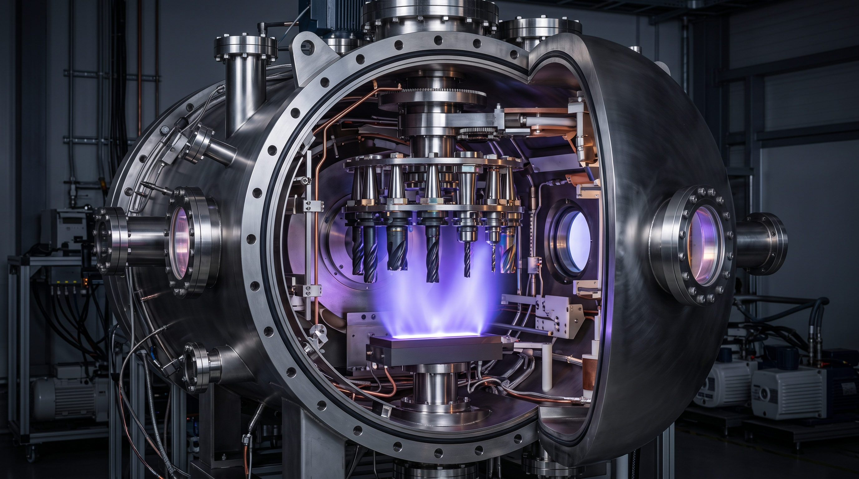
Every PVD route must create a vapour from a source, move that material to the parts and grow a film, but it can do so in different ways. Thermal or electron-beam evaporation, cathodic arc evaporation and sputtering are examples. Reactive gases may be introduced so that arriving metal species form compounds such as nitrides or oxides. Ion assistance and substrate bias can change energy at the growing surface.
That is why a request for “PVD coating” is incomplete. The supplier needs the substrate, heat treatment, previous coating, geometry, finish, tolerances, working environment and dominant failure mode. A coating intended to reduce adhesive wear on a forming tool may need a different architecture and finishing sequence than a decorative component or a part exposed to corrosion and repeated cleaning.
Sputtek’s PVD overview describes cathodic arc plus added sputtering capability. Its about page describes DC and pulsed cathodic arc, sputtering and hybrid approaches, along with in-house preparation and quality control. Those are first-party capability descriptions. The correct route for a part still requires application review and confirmation.
What happens from incoming part to finished coating
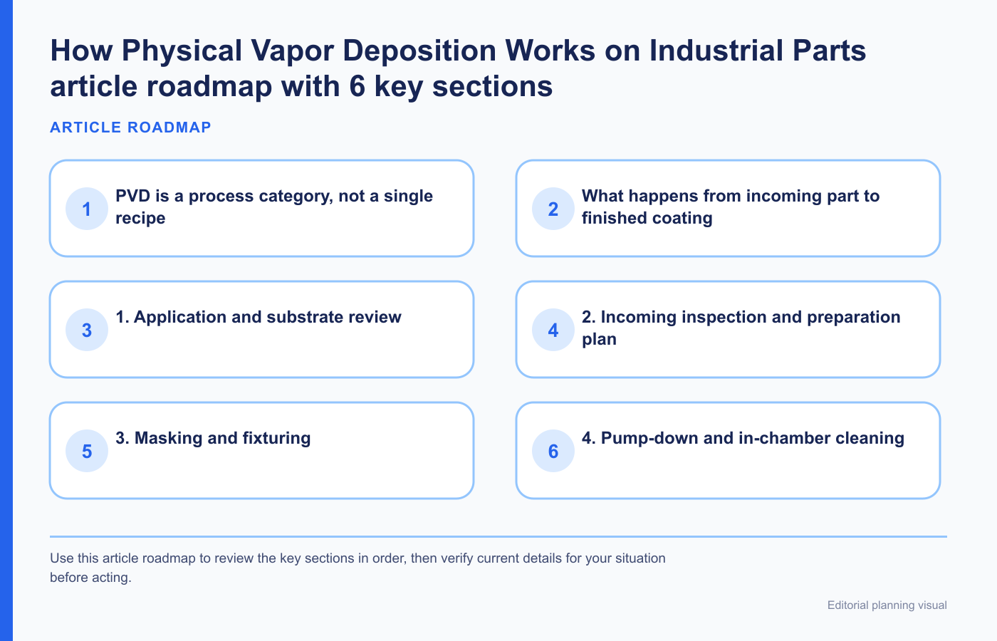
1. Application and substrate review
The process begins with what the part does and how it fails. Supply the substrate grade, hardness or heat treatment, dimensions, tolerances, current surface treatment, service temperature, lubrication, counterface and known wear evidence. The supplier can then screen whether the substrate and desired coating are compatible with the intended process window.
2. Incoming inspection and preparation plan
Coatings reproduce and sometimes emphasise the surface beneath them. Burrs, corrosion, deep grinding marks, residues and edge damage do not disappear inside the chamber. A 2024 review of cathodic arc PVD coatings discusses how contamination, substrate profile and preparation influence adhesion and coating morphology. Preparation may include stripping an old coating, degreasing, cleaning, polishing, blasting or other application-specific operations.
3. Masking and fixturing
Not every surface should be coated. Threads, fits, contact areas or datum surfaces may need masking. Fixtures must hold the part, provide electrical and thermal conditions where required, expose critical surfaces to the source flux and permit repeatable loading. Fixture contact points and shadowed regions belong on the drawing or process agreement.
4. Pump-down and in-chamber cleaning
The chamber is evacuated to reduce unwanted collisions and contamination. Heating and plasma or ion cleaning may be used within the qualified process. The exact sequence depends on the substrate and system. A peer-reviewed sputtering review emphasises the importance of cleaning and chamber process steps for adhesion.
5. Deposition and film growth
The source produces atoms, ions or clusters that travel toward the parts. They condense, nucleate and grow into a coating. Reactive gas, pressure, source power, substrate bias, temperature and time influence composition, residual stress, texture, morphology and thickness. Rotation can improve exposure, but it does not make every geometry equally accessible.
6. Cooling, unloading and post-treatment
Parts may need controlled cooling before handling. Depending on the specification, finishing or polishing can adjust surface condition after deposition. The supplier should protect critical surfaces and packaging from damage or contamination.
7. Inspection and release
Useful release criteria are tied to the application and drawing: visual condition, thickness at agreed locations, adhesion test, roughness, colour, dimensions or other verified characteristics. A certificate or inspection report should identify the actual requirement and method rather than using a vague “passed QC” statement.
How cathodic arc and sputtering differ
| Question | Cathodic arc | Sputtering |
|---|---|---|
| How source material is released | Intense arc spots create a highly ionised metal vapour | Energetic ions strike a target and eject atoms |
| Common engineering interest | High ionisation can support dense, adherent coatings under suitable conditions | Broad target flexibility and controlled film growth can suit many chemistries |
| Characteristic challenge | Macroparticles or droplets and associated surface defects need management | Deposition rate, target use, process time and film stress require optimisation |
| Selection basis | Substrate, geometry, required surface, coating architecture, throughput and service failure mode | |
The comparison is not a winner-take-all ranking. A review of PVD growth defects explains that defect origins and consequences differ across techniques. Filters, magnetic control, process optimisation and finishing can be used to manage arc-related particles, while sputtering has its own rate, contamination and stress controls. Hybrid systems can combine mechanisms, but their value must be judged against the part requirement.
Line of sight, holes and fixture shadows matter
PVD flux is directional enough that surfaces facing away from sources, deep recesses, narrow holes and fixture contacts may receive less coating than exposed faces. Part rotation and multi-axis fixtures improve coverage, but geometry still sets limits. Do not write “coat all surfaces uniformly” on a purchase order without identifying the measurement locations and acceptance range.
Supply a marked drawing with critical surfaces, no-coat areas, acceptable rack marks and dimensional tolerances. For holes or cavities, state the required depth of functional coverage. For sharp edges, ask how edge geometry and local coating stress are addressed. For assemblies, confirm whether parts must be disassembled and coated individually.
Quantity also affects fixturing and economics. A prototype may use a flexible fixture and broader process-development work; a recurring production lot may justify dedicated tooling and a controlled loading pattern. Tell the supplier the present lot, expected future volume and required traceability.
Hardness, friction and thickness are not stand-alone promises
Coating data sheets may list hardness, coefficient of friction, oxidation behaviour, colour or thickness. Those values are useful only with their test methods and conditions. A laboratory hardness result does not by itself predict tool life. Friction depends on the counterface, load, lubrication, temperature and surface condition. A thicker film is not automatically better because stress, adhesion, edge condition and tolerances still matter.
Build acceptance around the failure mechanism. If galling dominates, surface chemistry, finish and transfer behaviour may matter. If abrasive wear dominates, hardness and toughness within the coating-substrate system may be relevant. If impact or substrate deformation dominates, a hard film cannot compensate for inadequate support. Where the application is critical, plan a controlled trial and compare coated and current parts under the same operating conditions.
Sputtek’s first-party site discusses PVD for areas including stamping and machining and cutting. That shows service context, not a guarantee that a named coating will solve every wear problem. Send the actual failure evidence and let the recommendation be documented for the specific application.
A decision-ready PVD request for quote
| RFQ field | What to provide | Decision it supports |
|---|---|---|
| Part identity | Drawing, revision, photos and quantity | Scope, fixture design and traceability |
| Substrate | Alloy or grade, hardness, heat treatment and prior coating | Process compatibility and preparation |
| Geometry | Dimensions, critical faces, holes, edges and no-coat areas | Coverage, masking and measurement locations |
| Surface | Incoming finish, contamination restrictions and final roughness need | Preparation and post-treatment |
| Application | Loads, motion, temperature, lubrication, counterface and environment | Coating family and test plan |
| Failure mode | Wear photos, history, rejects and current life distribution | Useful performance objective |
| Acceptance | Thickness locations, adhesion method, dimensions, colour or documentation | Inspection and release |
| Logistics | Lot size, frequency, packaging, required date and shipping | Capacity and commercial quote |
Avoid prescribing a coating chemistry solely because it worked on a different part. If the specification is performance-based, state the operating requirement and jointly agree on the validation method. If it is process-based, define the allowable coating and controls clearly enough that incoming inspection can confirm compliance.
Common PVD mistakes and red flags
- Using “PVD” as the complete specification. It does not identify chemistry, architecture, process, thickness, surfaces or acceptance.
- Skipping substrate history. Unknown plating, nitriding, heat treatment or previous coating can change preparation and compatibility.
- Expecting coating to repair geometry. PVD is not a substitute for removing burrs, cracks or gross surface damage.
- Ignoring line-of-sight limits. Critical recessed areas need an explicit coverage discussion.
- Choosing the hardest number. Hardness without adhesion, toughness, substrate support and service context is incomplete.
- Comparing supplier data from different tests as if identical. Ask for methods and conditions.
- Ordering a large production lot before validating a changed system. Use representative trials and agreed success criteria where risk justifies them.
- Accepting a universal life-extension claim. Performance must be demonstrated in the actual process and operating window.
How to move from explanation to a controlled trial
- Identify the dominant failure with photos, measurements and process history.
- Confirm substrate, heat treatment, surface condition and dimensional constraints.
- Mark critical, no-coat and measurement locations on the drawing.
- Agree on preparation, coating family, thickness target, finishing and inspection.
- Run enough representative parts to observe both process variation and service variation.
- Compare against the current baseline using the same machine, material and operating conditions where possible.
- Review both part life and the broader economics: downtime, regrinding, stripping, rejects and logistics.
Frequently asked questions
Is PVD the same as sputtering?
No. Sputtering is one method within the broader PVD family. Cathodic arc and evaporation are other routes.
Does PVD coat every surface equally?
Not automatically. Source position, part rotation, geometry, recesses and fixture contacts influence coverage. Define critical locations.
Can PVD be applied over any substrate?
No universal answer is safe. Substrate composition, heat treatment, prior layers, temperature limits and preparation must be reviewed for the proposed process.
Will a harder coating always last longer?
No. Adhesion, toughness, residual stress, finish, substrate support and the actual wear system also influence performance.
Next step with Sputtek
Use Sputtek’s application enquiry route with a drawing, substrate and heat-treatment details, marked surfaces, quantity, service conditions, failure evidence and acceptance needs. Ask the response to identify the recommended process family, preparation, coating architecture, measurable release criteria, trial plan and confirmed logistics.
Editorial note: This explainer distinguishes general PVD science from Sputtek’s first-party capability descriptions. It does not publish a proprietary recipe or guarantee a coating result.