
Last updated: October 2026
By Ron – Sputtek | Refreshed October 2026
PVD coating at a glance
PVD, or Physical Vapor Deposition, applies a hard, dense film to a tool, component, mould, die, or other engineered surface inside a vacuum chamber. A solid source material is vaporized or sputtered, often reacts with nitrogen or a hydrocarbon gas, and condenses on prepared parts. The finished layer can change surface tribology while leaving the core material and geometry largely intact.
For manufacturing teams, the practical question is not simply whether PVD coating is hard. It is whether the selected film addresses the actual failure mode: abrasion, adhesive wear, galling, heat, corrosion, material pickup, or release problems. A good specification connects that failure mode to the substrate, operating temperature, surface finish, coating thickness, and acceptance tests.
- Typical thickness: approximately 1–5 μm, depending on application and tolerance.
- Common families: TiN, TiCN, TiAlN or AlTiN, CrN, and DLC.
- Typical process temperature: often about 150–500 °C, subject to chemistry and substrate limits.
- Common applications: cutting tools, stamping dies, mould components, forming tools, knives, shafts, and precision wear parts.
This guide explains how to select and prepare PVD coating for industrial use, including what Woodbridge-area manufacturers should discuss with a coating provider before sending production parts.
What is PVD coating?
Physical Vapor Deposition is a vacuum coating process that transfers material from a solid target or source to a component as a thin film. The chamber is evacuated, the surfaces are cleaned with plasma or ions, and the coating material is introduced under controlled electrical, gas-flow, temperature, and bias conditions. Fixtures usually rotate so the film reaches multiple faces of the load.
Different process routes influence the film’s density, adhesion, smoothness, residual stress, and ability to cover complex geometry. Sputtering can provide smooth, controllable films, while arc evaporation provides highly ionized material and strong adhesion; hybrid equipment can balance those characteristics. The appropriate route depends on the part, finish, tolerance, chemistry, and intended duty rather than on a single universal “best” method.
PVD should not be confused with consumer ceramic sealants, floor coatings, paint, or other macroscopic surface treatments. In industrial PVD, the layer is measured in microns. That thinness is useful when an edge, bore, datum, or precision fit must remain close to its original dimensions.
Why PVD coating matters to Woodbridge manufacturers
PVD coating can help a production team manage wear, friction, pickup, corrosion, and maintenance without resorting to a thick build that changes a component’s dimensions. The benefit is greatest when the surface is the limiting factor and the underlying tool or component remains structurally suitable.
Woodbridge manufacturers often work within connected supply chains serving automotive, aerospace, medical, packaging, and other precision industries. A coating decision therefore has to account for more than hardness. Repeatable preparation, documented recipes, inspection records, batch capacity, and communication about tolerances can be important when a coated part moves from a trial into recurring production.
What PVD can improve
- Abrasive wear: hard films can protect cutting edges, dies, guides, and sliding surfaces from repeated contact with abrasive material.
- Adhesive wear and galling: selected low-friction films can reduce material pickup where two surfaces slide under load.
- Heat-related wear: TiAlN or AlTiN are candidates for applications where hot cutting or elevated surface temperature is a concern, subject to substrate compatibility.
- Corrosion and washdown: CrN can be considered where corrosion resistance and a balanced wear response are required.
- Release and sliding: DLC is often evaluated for low-friction interfaces, mould components, and forming applications.
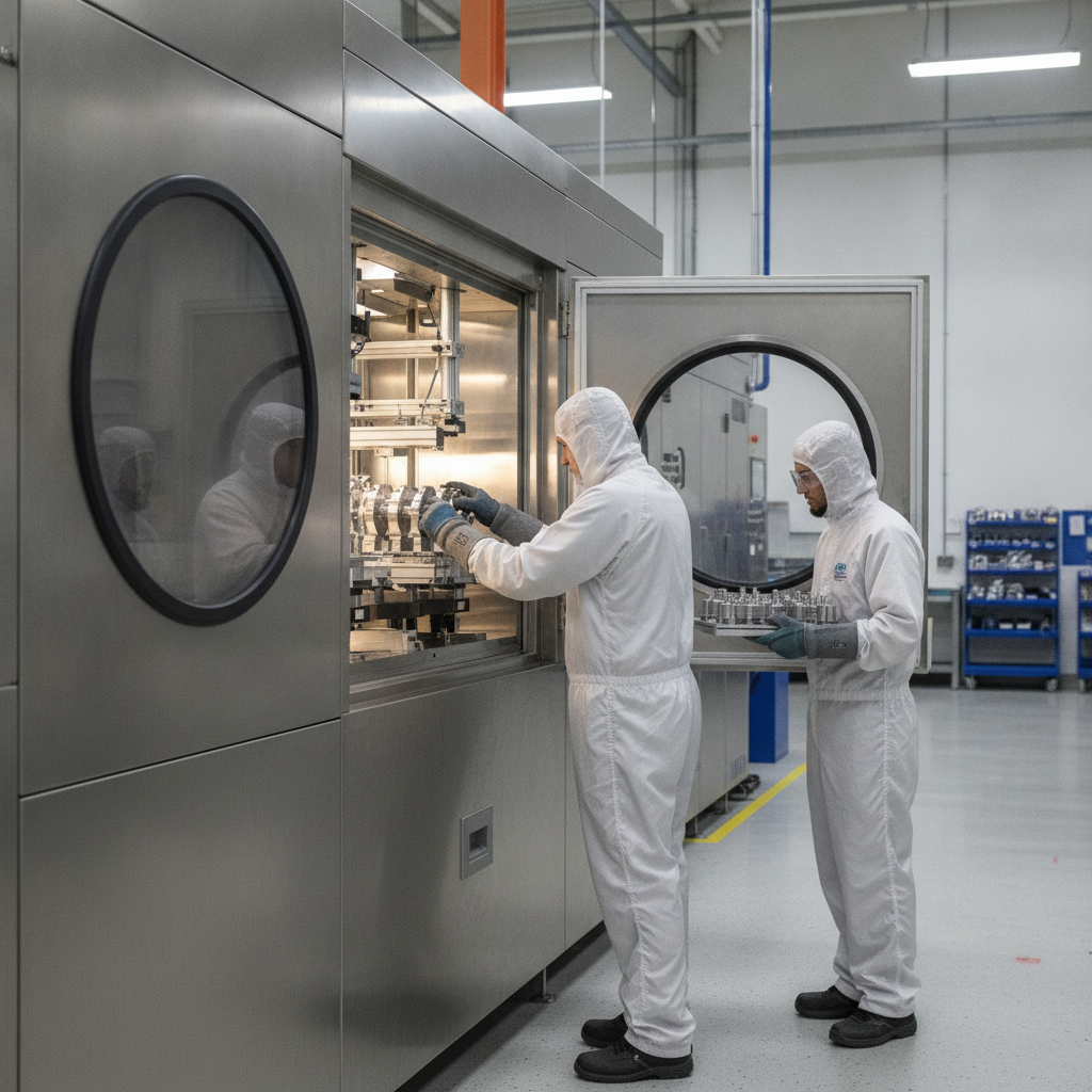
Sputtek operates from a 15,000-square-foot Greater Toronto Area facility and supports prototyping through high-volume manufacturing. Its confirmed capabilities include in-house preparation and quality control, as well as SPUN 2,000 and SPUN 4,000 systems with stated load capacities of approximately 1,200 kg and 3,000 kg per cycle respectively. Those capacities are relevant when a supplier must scale a validated process without changing the basic production route.
Local planning considerations
For a Woodbridge program, plan logistics around heavy tooling, batch consolidation, and the condition in which parts arrive. Provide drawings, substrate and heat-treatment details, areas to mask, current surface finish, and the dominant failure mode before the first quotation. Clear information reduces the chance that a coating trial is asked to compensate for an unsuitable edge, contaminated surface, or poorly defined operating condition.
How the PVD coating process works
A reliable PVD coating process begins before the parts enter the chamber. The provider needs to understand the substrate, dimensions, existing finish, working temperature, contact materials, lubrication, and reason for failure. That information guides preparation, masking, fixture orientation, chemistry, and inspection.
- Incoming inspection: Confirm dimensions, substrate, heat treatment, surface condition, and worn or damaged zones. Record any features that must remain uncoated.
- Cleaning and degreasing: Remove oils, residues, polishing compounds, and other contaminants. Ultrasonic cleaning and controlled rinsing may be used according to the part and process.
- Surface preparation: Polish, lap, blast, or microblast where appropriate. Preparation must improve adhesion without damaging a cutting edge, datum, seal surface, or critical geometry.
- Fixturing and masking: Position parts for line-of-sight access and consistent rotation. Mask bores, fits, threads, and faces that must remain bare or within a specified tolerance.
- Vacuum pump-down: The chamber is evacuated to remove air and contaminants. Exact pressure and process conditions vary by equipment and recipe.
- Plasma cleaning: Ionized gas removes remaining surface contamination and activates the substrate immediately before deposition.
- Deposition: The selected target material is vaporized or sputtered. Reactive gases such as nitrogen or hydrocarbon gases may be introduced to create the required compound or carbon-based film.
- Cooling and unloading: Controlled cooling helps protect the substrate and coating. Parts are then inspected before release or any specified finishing operation.
- Quality verification: Thickness, appearance, adhesion, hardness response, dimensions, and other application-specific criteria are checked and recorded.
Cycle duration depends on the recipe, load density, part mass, target thickness, and equipment. A heavy die or densely packed fixture can require more heating and cooling time than a small tool batch. Ask the supplier how the process is controlled across the load, not only how long a nominal cycle takes.
How to choose a PVD coating chemistry
The correct chemistry depends on the failure mode and operating environment. Colour can help identify a coating family, but it is not a sufficient selection method. Substrate, temperature, counterface, lubrication, surface finish, edge preparation, and dimensional tolerance should all be part of the decision.
TiN for general-purpose wear
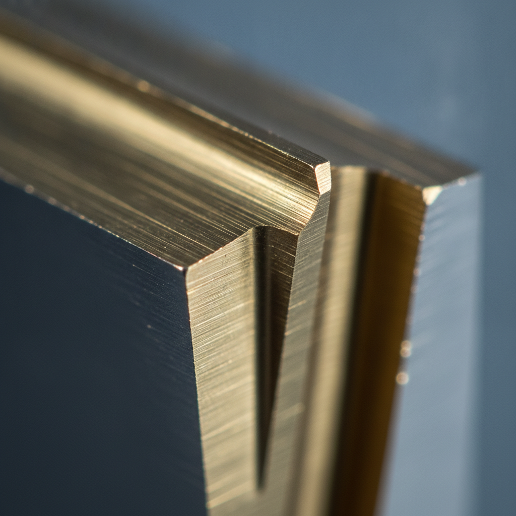
TiN is a widely used gold-coloured coating for tools, dies, fixtures, and other components where general wear resistance is needed. It is a practical starting point for many steel applications, but it should not be selected automatically when the dominant problem is high heat, severe galling, or corrosion.
TiCN for abrasive or sliding wear
TiCN is commonly considered when higher hardness or abrasion resistance than a general-purpose TiN route is desirable. The substrate and application still determine whether it is appropriate, particularly where impact, thermal cycling, or a sensitive edge is involved.
TiAlN and AlTiN for hot applications
TiAlN and AlTiN are candidates for high-speed machining, hot forming, and other applications where elevated temperature and oxidation resistance influence wear. Their performance depends on the actual cutting or forming conditions, so the coating should be validated against the production settings rather than judged from nominal hardness alone.
CrN for corrosion and material compatibility
CrN offers a useful combination of wear and corrosion resistance for components exposed to moisture, washdown, or demanding contact conditions. It can be considered for mould components, food and packaging equipment, and other parts where surface condition and cleaning exposure matter.
DLC for low friction and anti-galling
DLC, or diamond-like carbon, is a family of carbon-based coatings rather than one single material. It is often evaluated where low friction, reduced pickup, release, or anti-galling behaviour is more important than maximum hot-cutting performance. A DLC specification should identify the substrate, counterface, lubrication state, film type, thickness, and test conditions.
For a focused explanation of carbon-based options, see Sputtek’s DLC coating process overview. The broader DLC coating services guide can help compare application requirements before requesting a trial.
Comparison with CVD and HVOF
| Method | Typical scale | Primary advantage | Common decision point |
|---|---|---|---|
| PVD | Thin films, often 1–5 μm | Hard, functional surface with limited dimensional change | Precision wear, friction, heat, or release requirements |
| CVD | Often thicker than PVD | High-temperature deposition and hard surface films | Suitable substrates and geometry can tolerate the process temperature |
| HVOF or Thermospray | Typically tens to hundreds of microns | Thick wear, corrosion, or dimensional restoration layers | A part needs a build-up, repair, or substantial barrier |
PVD and HVOF are not direct substitutes in every job. PVD may provide the final tribological surface after a thicker process restores a worn diameter, while a thermal-spray route may be more appropriate when a component needs measurable material added. Sputtek’s metal vapor deposition overview places PVD within the wider family of deposition technologies.
Design, preparation, and quality assurance
Most coating problems are easier to prevent than to correct after deposition. A short technical review should identify the failure mode, substrate, edge condition, surface finish, coating boundaries, dimensions, operating temperature, lubrication, and inspection method.
Specify the part before specifying the film
- Provide the substrate grade, hardness, heat-treatment condition, and any tempering or dimensional restrictions.
- Mark critical edges, bores, datum faces, threads, sealing areas, and surfaces that must be masked.
- Describe the contact pair, load, speed, temperature, lubrication, contaminant, and production material.
- Separate the original failure from secondary damage such as chipping, pickup, corrosion, or distortion.
Control surface preparation
Cleanliness is essential because oil, polishing residue, oxides, and handling contamination can weaken adhesion. Surface roughness should suit the application: a sliding or release surface may require a smoother finish, while an appropriate preparation route can support mechanical and chemical bonding. Blasting or microblasting must be controlled so it does not round a precision edge or alter a critical geometry.
Plan edges, masking, and tolerances
A micron-scale coating still matters when a bore, clearance, cutting edge, or seal is tightly specified. Define the allowable coating boundary and post-coating finish before processing. Cutting tools may benefit from a controlled hone, while sharp functional edges, threads, and fits may require special masking or inspection.
Use a documented acceptance plan
Agree on the measurements that determine acceptance. Depending on the application, this can include coating thickness by an appropriate method, adhesion testing, hardness response, visual inspection, surface roughness, dimensions, and functional wear testing. A run card should link the part number and substrate to preparation, fixture orientation, chemistry, temperature, gas conditions, cycle, and inspection results.
In-house preparation, stripping, polishing, lapping, and quality control can simplify feedback during a trial. It also makes it easier to investigate whether a result came from the coating, the substrate, the surface finish, or the application conditions.
Where engineers commonly evaluate PVD coating
Stamping and forming dies
For stamping, the evaluation often centres on galling, pickup, abrasive wear, and surface finish. TiAlN, CrN, DLC, or another candidate may be considered depending on the sheet material, contact pressure, lubrication, die temperature, and whether the problem occurs on a cutting or sliding zone.
Cutting tools
End mills, drills, inserts, and other tools require a chemistry matched to cutting speed, workpiece material, coolant, edge preparation, and heat generation. A coating trial should measure tool wear and part quality under repeatable production conditions rather than relying only on a coupon test.
Injection mould components
Ejector pins, cores, slides, and cavity details may benefit from reduced friction, release improvement, or resistance to wear and corrosion. DLC is often investigated for low-friction release duties, while CrN may be considered where moisture, washdown, or corrosion is part of the operating environment.
Die-casting and nonferrous applications
Die-casting cores and forming surfaces can experience soldering, erosion, thermal cycling, and material pickup. Chemistry selection must account for the alloy being processed, temperature, release agent, and the ability of the substrate to tolerate the deposition cycle.
Knives, valves, and sliding components
Industrial knives, valve stems, guides, and other sliding parts are usually assessed for edge retention, scoring, friction, corrosion, or galling. The counterface and lubrication state are especially important: a coating that performs well in one pair may require a different specification in another.
A practical PVD coating selection checklist
Before requesting a production quotation or trial, assemble the information below. It gives the coating engineer enough context to recommend a shortlist and define a useful validation plan.
- Identify the dominant failure: abrasion, galling, heat, corrosion, pickup, release, or dimensional wear.
- Document the substrate grade, hardness, heat treatment, and any temperature restriction.
- Record the counterface, workpiece material, load, speed, temperature, lubrication, and cleaning exposure.
- Measure or specify the existing surface finish and edge condition.
- Mark surfaces to coat, surfaces to mask, and maximum dimensional change.
- Select two or more candidate chemistries only when their purposes are clearly different.
- Define thickness, adhesion, roughness, dimensional, and functional pass/fail criteria.
- Compare trial results using the same production conditions and inspection method.
This approach prevents a common mistake: asking for the hardest available coating when the real issue is poor preparation, an unsuitable edge, excessive heat, or a mismatch between the coating and counterface.
Frequently asked questions about PVD coating
What is PVD coating used for?
PVD coating is used to improve the surface performance of tools, dies, mould components, cutting edges, sliding parts, and other engineered components. It is commonly evaluated for wear, friction, galling, heat-related degradation, corrosion, pickup, and release problems. The coating must be matched to the substrate and operating conditions.
How thick is a PVD coating?
Many industrial PVD applications use a film in the approximate range of 1–5 μm. The required thickness depends on wear duty, edge retention, surface finish, fit tolerance, and the selected chemistry. A thicker film is not automatically better if it changes a critical dimension or increases stress at an edge.
What temperature does PVD coating use?
Many PVD processes operate within an approximate 150–500 °C range, but the actual window depends on equipment, chemistry, fixture load, and substrate. Aluminium, copper, hardened steels, and other temperature-sensitive materials may require a lower-temperature route or additional review. The coating supplier should confirm compatibility with the part’s heat treatment and allowable temper change.
When should I choose DLC instead of TiN or TiAlN?
Consider DLC when low friction, anti-galling, material release, or sliding performance is the main requirement. TiN is a practical general-purpose wear option, while TiAlN or AlTiN is often considered for hot cutting and oxidation-related demands. Final selection should use the counterface, temperature, lubrication, substrate, and validation results rather than colour or hardness alone.
Next steps for a PVD coating project
PVD coating is most effective when it is treated as an engineered surface solution rather than a generic finish. Define the failure mode, confirm the substrate and temperature window, prepare the surface carefully, select a chemistry for the duty, and document thickness, adhesion, dimensions, and functional performance.
For a Woodbridge manufacturing program, begin with one representative part and a clear comparison between the current condition and the proposed coating. Sputtek supports PVD and DLC programs from prototyping through high-volume production, with in-house preparation and quality control for repeatable process development.
When you are ready to review a part, contact Sputtek with its drawing, substrate, failure history, operating conditions, and required tolerances so the coating recommendation can be tied to a measurable production objective.