
Last updated: October 2026
Diamond-like carbon (DLC) is a thin, amorphous carbon coating used to reduce friction, adhesive wear, galling, and material pickup on tools and precision components. It is deposited in a vacuum using processes such as sputtering, plasma-assisted chemical vapour deposition (PACVD), or filtered cathodic arc, with the film and interlayer selected for the application.
This guide explains what happens before, during, and after deposition. It is written for engineers and manufacturing teams evaluating DLC for stamping tools, injection-mould components, carbide cutting tools, sliding parts, and other wear-critical surfaces. Sputtek supports prototype-to-production coating programs from its Woodbridge, Ontario facility.
What is DLC coating?
DLC, or diamond-like carbon, is a family of carbon-based thin films containing different proportions and arrangements of sp2 and sp3 bonding. Unlike crystalline diamond, DLC is amorphous. Its practical value comes from combining high hardness, low shear, chemical stability, and a relatively low coefficient of friction in a coating that changes part dimensions only slightly.
DLC is not one universal recipe. Hydrogenated amorphous carbon, metal-doped DLC, and hydrogen-free tetrahedral amorphous carbon (ta-C) can have different stress, hardness, friction, and temperature characteristics. A coating supplier therefore has to match the film architecture to the substrate, counterface, lubrication regime, load, and part geometry.
Where DLC is useful
- Stamping and forming: DLC can reduce material pickup and galling on correctly prepared forming surfaces.
- Plastic injection tooling: Coating ejector pins, slides, and other moving features can help reduce scuffing and sticking.
- Non-ferrous machining: DLC is commonly evaluated on carbide tools used with aluminium and other materials where built-up edge is a concern.
- Precision components: Shafts, plungers, pins, and valve components may benefit from lower friction during boundary-lubricated or start-up conditions.
Performance is not guaranteed by the coating name alone. Surface finish, edge preparation, heat treatment, contact pressure, counterface material, lubrication, and cleaning all influence the result.
How the DLC coating process works
A production DLC coating process normally follows a closed-loop sequence: review the part requirements, inspect incoming components, clean and mask them, activate the surface, apply an adhesion-promoting interlayer, deposit the carbon film, cool and unload the parts, finish them if required, and complete quality checks. Each stage can affect adhesion and film uniformity, so the process should be documented rather than treated as a single chamber operation.
1. Review the part and inspect incoming condition
Before coating, confirm the drawing revision, substrate, heat treatment, hardness, critical dimensions, functional surfaces, and any areas that must remain uncoated. The coating plan should also identify threads, bores, datum surfaces, sharp edges, sealing lands, and post-coating finishing limits.
Incoming inspection establishes a baseline. Record visible damage and measure critical roughness or dimensions where appropriate. If the part arrives with burrs, grinding marks, corrosion, embedded media, or an unknown heat history, resolve that condition before choosing a deposition recipe.
2. Clean and prepare the surface
Oil, coolant, fingerprints, polishing compound, and handling residue can prevent the film from bonding to the substrate. A controlled cleaning sequence may combine alkaline cleaning, solvent cleaning, rinsing, drying, and ultrasonic treatment, depending on the material and contamination. Parts should be handled with clean gloves after preparation and protected from recontamination.
Surface preparation is application-specific. Functional contact zones generally need a fine, consistent finish; abrasive preparation may be appropriate only on selected areas and must be kept away from critical geometry. The preparation record should identify the process used, the part orientation, and any media or tooling that could affect the surface.
3. Mask critical areas and load the fixture
Masking prevents deposition on threads, precision fits, sealing lands, electrical contacts, or other areas that must retain their original dimensions or function. The masking design should use repeatable datums and clearly identify which features are intentionally coated. Sharp edges may need a small edge break because an extremely thin edge can concentrate stress and chip during service.
Fixturing controls coverage. Parts should be spaced so they do not shadow one another, and the rack should support the required rotation or planetary motion. Recording part positions and orientation makes later batches easier to reproduce, especially when a coating program includes matched tools or multiple cavities.
4. Pump down, heat, and activate the surface
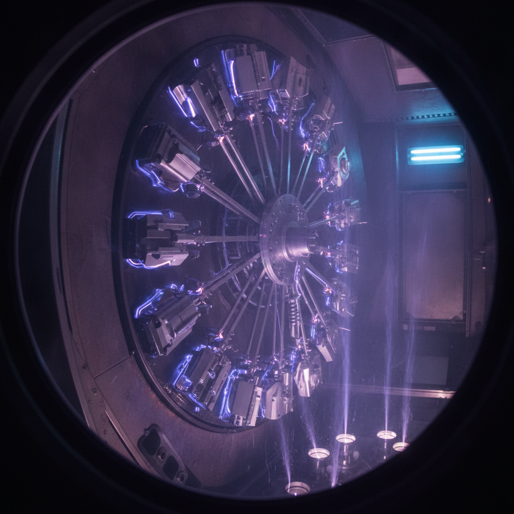
Loaded parts enter the vacuum chamber, which is evacuated to the pressure required by the selected process. A controlled heat soak helps equalise the substrate temperature, but the allowable temperature must be checked against the part’s tempering and dimensional requirements. Tool steel, stainless steel, carbide, and heat-treated components do not share the same thermal limits.
Before film growth, plasma or ion cleaning removes remaining surface contamination and activates the substrate. This step can use argon or another process gas, with bias, time, and energy controlled to avoid damaging edges or changing the surface beyond the specification. Good activation improves the consistency of the interface between the substrate and the coating system.
5. Deposit the interlayer and carbon film
An adhesion-promoting interlayer, such as a titanium- or chromium-based layer, can provide a graded transition between the substrate and the carbon film. The choice and thickness depend on the substrate, DLC family, process route, and stress requirements. Some applications may use additional transition layers rather than a single interface.
The carbon layer is then deposited using the selected PVD, PACVD, PECVD, or filtered-arc route. During growth, the process team controls pressure, gas flow, power, bias, temperature, time, and fixture motion. Film thickness is chosen for the load and geometry; adding thickness indiscriminately can increase stress, affect clearances, or make an edge more vulnerable.
6. Cool, unload, and finish the parts
Controlled cooling reduces thermal shock and protects thin edges and delicate features. Venting and handling should be managed so that freshly coated surfaces are not contaminated or scratched. Parts should be bagged or otherwise protected if they are moving to a finishing or inspection operation.
Some components require a light lapping or polishing step to restore a specified surface finish or remove a small amount of roughness created by deposition. Finishing must be controlled: excessive polishing can reduce the coating thickness or alter a functional profile. The final process should therefore define both the coating target and the allowable post-treatment.
Which DLC deposition method should you choose?
The method should follow the part, not the other way around. Compare the geometry, substrate temperature limit, required film structure, internal features, edge sensitivity, and acceptable stress before selecting a recipe. The table below is a starting point for a technical discussion, not a substitute for a coating trial.
| Method | Useful starting point | Primary decision considerations |
|---|---|---|
| PVD sputtering | Flat or moderately complex tools, inserts, and components requiring controlled, lower-stress films | Line-of-sight coverage, fixture rotation, film uniformity, and substrate temperature |
| PACVD or PECVD | Complex three-dimensional components and features where conformal coverage is important | Part geometry, plasma access, hydrogen content, adhesion system, and process temperature |
| Filtered cathodic arc | Applications evaluating dense, hydrogen-free ta-C films and very low friction | Higher intrinsic stress, substrate robustness, particle control, and edge design |
External technical descriptions also identify cleaning, fixture rotation, pump-down, preheating, ion bombardment, underlayer deposition, carbon growth, and cooling as important stages in the overall sequence. These stages are consistent with the process logic described here, but the exact recipe must be validated for the customer’s component.
Substrates and design rules for DLC
DLC can be evaluated on tool steels, selected stainless steels, nitrided steels, tungsten carbide, and other compatible substrates. The substrate must have the required hardness and heat history before coating. A film cannot compensate for a soft, unstable, cracked, or poorly finished foundation.
- Control roughness: Define a target for each functional zone rather than applying one value to the entire part. Fine contact surfaces often require polishing before coating.
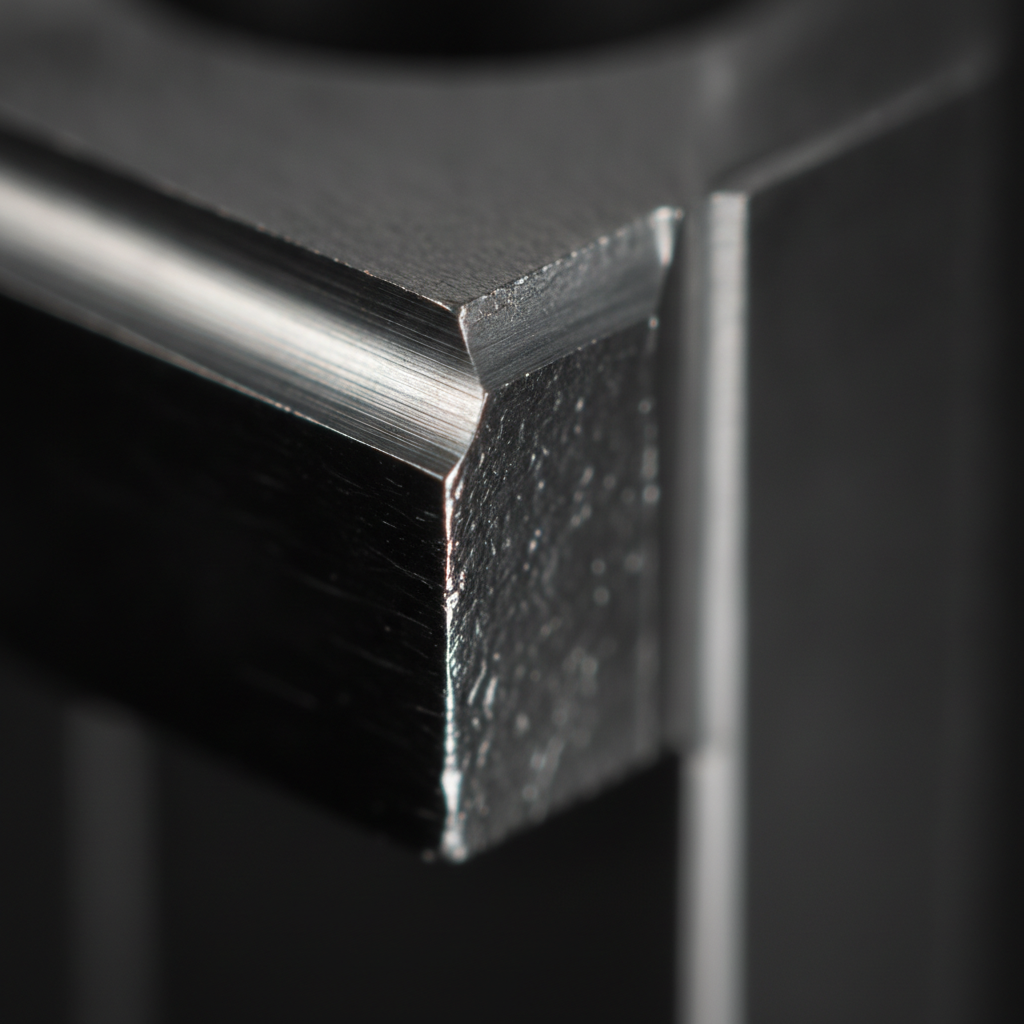
- Remove burrs: Burrs and sharp, fragile edges can interfere with masking, concentrate stress, and chip during use.
- Protect fits and datums: Confirm the coating allowance for threads, bores, shut-offs, seals, and sliding clearances.
- Plan for coverage: Deep bores, undercuts, and recessed features may need special fixturing or a different deposition method.
- Check heat history: Confirm that the process temperature and dwell will not compromise temper, hardness, dimensional stability, or an existing treatment.
For a broader explanation of how vacuum deposition works, see the PVD coating guide. It provides useful context when DLC is being compared with other physical-vapour-deposition families.
Quality control and acceptance checks
A reliable DLC program defines acceptance criteria before the first production batch. The criteria may cover thickness, adhesion, roughness, coverage, appearance, dimensions, hardness, and traceability. Witness coupons can help the team monitor a process without damaging every production component.
Thickness and coverage
Thickness can be checked using a method suited to the coating and substrate, such as a calotte or ball-crater measurement, X-ray fluorescence, or coupon-based metrology. Readings should be taken at locations that represent the functional surface and the fixture position. Complex parts may also require microscopy or borescope inspection to check areas that are difficult to see directly.
Adhesion and surface condition
Adhesion testing should record the test method, critical load where applicable, and failure mode rather than reporting only a pass or fail. Roughness should be measured before and after any lapping operation, especially on sealing, sliding, or ejection surfaces. Visual inspection can identify particles, pinholes, edge damage, discoloration, or areas affected by masking.
Traceability and controlled records
Batch records should connect the customer part or lot to the cleaning route, mask plan, fixture position, recipe version, temperature history, pressure history, inspection results, and any rework. Sputtek states that its processes operate under ISO 9001:2015 and Nuclear N299.3 controls, which supports documented and repeatable quality workflows for applicable programs.
For teams comparing process families and equipment considerations, the PVD types overview explains how different deposition approaches vary in application fit.
Common DLC process problems and corrective actions
Poor or inconsistent adhesion
Investigate contamination, cleaning time, plasma activation, substrate hardness, interlayer selection, and film stress. A failure that appears to be a coating problem may originate in polishing residue, an unstable heat treatment, or a surface that was touched after cleaning.
Uneven thickness or incomplete coverage
Review the fixture layout, line of sight, part spacing, rotation, and chamber loading. Deep features may need a different orientation, additional motion, or a conformal plasma process. Coverage should be evaluated on representative parts rather than assumed from a flat witness coupon alone.
Edge chipping or premature wear
Check edge preparation, coating thickness, stress, cooling, handling, and the actual contact load. A thinner film, a different interlayer, a gentler edge break, or a lower-stress DLC family may be more appropriate than simply repeating the original run.
Friction remains higher than expected
Confirm the counterface, lubrication, roughness, film type, and post-coating finish. DLC lowers friction in suitable contact conditions, but it does not remove the need to control alignment, pressure, debris, and lubrication. Testing should reproduce the real operating pair whenever possible.
Planning a production DLC program
Start with a representative component and define the failure mode the coating is expected to address. Gather the substrate specification, heat-treatment information, drawing and tolerance data, contact materials, operating temperature, lubrication conditions, current life or wear issue, and cleaning restrictions. These details allow the coating team to propose a method and test plan based on the application rather than a generic film label.
For repeat production, qualify the process using agreed samples and acceptance criteria. Run comparable parts in the same fixture where possible, retain witness coupons, and document any changes to polishing, masking, loading, or recipe parameters. Stable preparation often contributes as much to repeatability as the chamber recipe itself.
Sputtek’s DLC coating services guide describes how a service program can connect application requirements with coating selection, preparation, and production support. For teams comparing fixturing and deposition routes in more detail, the PVD methods guide is a useful next step.
Frequently asked questions about the DLC coating process
How long does the DLC coating process take?
There is no single duration for every part. Cleaning, masking, chamber loading, pump-down, activation, interlayer deposition, carbon growth, cooling, inspection, and any lapping or polishing all contribute to the schedule. The batch size, geometry, required thickness, and qualification work should be reviewed before a delivery commitment is made.
What thickness is typical for DLC?
Many engineering DLC applications use a thin film measured in micrometres, with the suitable range determined by geometry, stress, load, and clearance. A thicker coating is not automatically more durable. The final target should be established with the coating supplier and verified using an agreed measurement method on the part or a representative coupon.
Can DLC be applied to hardened steel or carbide?
Yes, hardened tool steels and tungsten carbide are common candidates for evaluation, provided their surface condition, heat history, geometry, and cleaning requirements are compatible with the selected process. The substrate should be checked for hardness, cracks, burrs, and dimensional stability before coating. Stainless and nitrided steels may also be suitable, but the recipe and adhesion system require application-specific review.
What information should I provide for a DLC coating quotation?
Provide the drawing and revision, material and heat treatment, quantity, critical dimensions, functional surfaces, current surface finish, operating temperature, contact or counterface material, lubrication conditions, and the failure mode you want to address. Include photographs or samples when geometry, masking, or internal features are important. This information helps determine whether sputtering, PACVD, filtered arc, or another route is appropriate.
Discuss your DLC coating process
DLC performs best when coating selection, surface preparation, fixturing, and inspection are planned as one process. If you are evaluating a new component or troubleshooting wear on an existing tool, Sputtek can review the substrate, geometry, finish, temperature window, and production requirements at its Woodbridge facility. Contact Sputtek to discuss a coating trial or production program.