Physical vapor deposition methods are vacuum thin-film techniques—like sputtering, cathodic arc, and evaporation—that deposit dense, hard, wear-resistant coatings. At 110 Sharer Rd in Woodbridge, Sputtek uses PVD to increase tool life, reduce friction, and stabilize throughput for regulated manufacturing. This guide explains what PVD is, how it works, method types, best practices, and when to pair PVD with Thermospray (Pulsed HVOF).
By Ron — Last updated: 2026-06-09
Overview at a Glance
Physical vapor deposition (PVD) is a family of vacuum coating methods that vaporize a solid source and condense it onto parts as a thin, dense, adherent film. It boosts hardness, cuts friction, and resists corrosion. Engineers use PVD to extend tool life, stabilize quality, and shorten maintenance windows in production.
This complete guide is written for manufacturing engineers, toolmakers, quality leaders, and procurement teams evaluating PVD in real production. You’ll find definitions, method comparisons, decision frameworks, and shop-floor best practices that prevent bad coats and save time.
- What PVD is and how it works (vacuum, plasma, and adhesion fundamentals)
- The main physical vapor deposition methods and when to use each
- Actionable process checks that stop flaking, pinholes, and poor adhesion
- Decision tools to match methods to substrates, temperatures, and geometries
- Real examples from stamping, molding, machining, and component coating
- Key specs to track: base pressure (≤1×10⁻⁶ Torr), ion energy (10–200 eV), deposition rate (0.5–10 μm/hr), film hardness (15–30 GPa), and coefficient of friction (0.05–0.3 for DLC/TiN families).
What Is Physical Vapor Deposition?
Physical vapor deposition is a set of vacuum processes that physically eject atoms from a target (by sputtering, arc, or evaporation) and condense them on a substrate as a thin film. The result is a hard, dense, well-adhered coating that improves wear, friction, and corrosion resistance on tools and components.
In plain terms, PVD turns a solid into a vapor under high vacuum and guides it to your parts. The vapor re-solidifies on the surface, forming a coating that’s typically 1–10 μm thick with high hardness and strong adhesion.
- Common chemistries: TiN, TiCN, AlTiN, CrN, ZrN, DLC (carbon-based), and multilayers.
- Typical thickness: 1–5 μm for cutting tools; 0.5–3 μm for molds and components.
- Temperature range: About 150–500 °C depending on method and substrate.
- Adhesion mechanisms: Mechanical interlocking (after blasting/lapping), interdiffusion, and ion-assisted bonding.
At Sputtek, PVD is paired with in-house preparation (sandblasting, microblasting, cleaning) and post-processing (stripping, polishing, lapping, QC lab) to keep adhesion consistent from prototype to volume lots.
Why PVD Methods Matter
Choosing the right PVD method determines coating density, adhesion, residual stress, and thermal load. Method fit impacts scrap rates, changeover time, and the interval between tool pulls. The wrong process can cause flaking or soft films; the right one can double or triple service life.
Method selection is not academic—it’s production economics. A 2–4× life extension for stamping dies or molds means fewer pulls, fewer changeovers, and steadier Cp/Cpk. Dense, high-adhesion films also stabilize surface finish, reducing rework.
- Wear performance: Denser films (arc, HiPIMS sputter) often yield better abrasion resistance.
- Thermal sensitivity: Lower-temperature options (DLC variants) protect temper of hardened steels and sensitive alloys.
- Geometry coverage: Ionization level and part biasing influence sidewall coverage and line-of-sight limits.
- Throughput: Deposition rate (0.5–10 μm/hr) and batch capacity drive takt time and planning.
In our experience supporting automotive, aerospace, medical, pharma, oil and gas, and nuclear tooling, matching method to substrate and load case is the single most important lever for predictable life gain.
How Physical Vapor Deposition Works
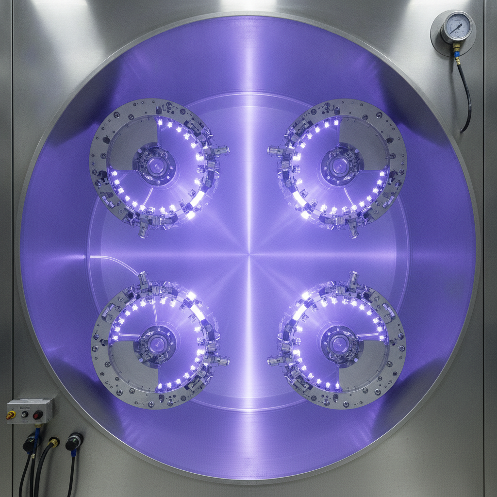
PVD runs in vacuum. A source is ionized or heated so atoms leave the target, travel through a low-pressure plasma, and condense on the part. Substrate bias and temperature control tune film density, stress, and adhesion so the coating survives real cutting, forming, and sliding loads.
Here’s the physics in shop-floor terms. We evacuate the chamber (typically ≤1×10⁻⁶ Torr base). We ignite a plasma using argon and reactive gases. Energy dislodges atoms from a target. A negative bias on the parts attracts ions that compact the film, while controlled temperature manages stress and metallurgical stability.
- Vacuum and gas: Lower pressure increases mean free path; reactive gases form nitrides/carbides (e.g., N₂ for TiN, C₂H₂ for DLC).
- Ion energy: 10–200 eV is common; enough for densification, not so high that the film microcracks.
- Substrate prep: Clean, activated surfaces (after blasting, ultrasonic cleaning, bake-out) are essential to adhesion.
- Bias and temperature: Bias densifies; temperature crystallizes phases (e.g., AlTiN’s thermal stability for hot cutting).
Well-controlled PVD produces films with hardness around 15–30 GPa, coefficients of friction as low as 0.05–0.3 (for DLC and TiN-class films), and adhesion that withstands >60 N critical loads in scratch testing.

Types of PVD Methods
The main PVD families are sputtering (DC, RF, magnetron, HiPIMS), cathodic arc (including filtered arc), and thermal evaporation (resistive, e‑beam, ion plating/IBAD). Each balances ionization, temperature, and rate differently to target hardness, stress, coverage, and throughput for specific parts.
1) Sputtering (DC/RF Magnetron, HiPIMS)
- How it works: Argon ions knock atoms off a target; magnets confine plasma to raise rate and ionization.
- Strengths: Excellent uniformity; low to moderate substrate temperature; smooth surfaces; tight thickness control.
- Variants: DC (conductive targets), RF (insulators), mid-frequency, and HiPIMS (high ionization for dense films).
- Applications: Cutting tools (AlTiN), molds (CrN), components (TiN decorative/functional), and barrier layers.
- Typical numbers: 1–5 μm/hr; hardness 15–30 GPa (chemistry dependent); bias ~−50 to −200 V.
2) Cathodic Arc (Filtered Arc)
- How it works: An electric arc vaporizes target spots into a highly ionized metal plasma.
- Strengths: Very dense films and high adhesion; great for extreme wear; fast deposition.
- Considerations: Droplets/macroparticles can roughen surfaces; filtered arc mitigates this with magnetic filtering.
- Applications: Heavy-duty stamping dies, forming tools, high-load sliding components.
- Typical numbers: 3–10 μm/hr; high ion energy; strong bias compaction produces top hardness.
3) Thermal Evaporation (Resistive, E‑Beam) and Ion Plating/IBAD
- How it works: Heat (filament or electron beam) evaporates source material that condenses on parts.
- Ion plating/IBAD: Adds ion assistance to densify and improve adhesion; good for temperature-sensitive substrates.
- Strengths: Simple, fast line-of-sight coating; lower substrate temperatures possible.
- Applications: Optical/reflective layers, decorative finishes, certain tool coatings with ion assist.
- Typical numbers: 1–8 μm/hr; lower intrinsic stress with ion assist; smooth finishes.
4) DLC (Diamond-Like Carbon) via PVD Routes
- How it works: Carbon-based plasmas (often hydrocarbon gases) deposit amorphous carbon films with sp²/sp³ mix.
- Strengths: Ultra-low friction (down to ~0.05), good wear on non-ferrous and hardened steels, low temperature compared to nitrides.
- Applications: Injection pins, sliding components, medical instruments, valve train parts.
For a deeper primer on coatings like DLC and nitride systems, see Sputtek’s DLC coating guide and our overview on choosing the best PVD type.
Choosing the Right PVD Method
Select a PVD method by balancing substrate temperature limits, geometry coverage, required hardness, and production takt. Sputtering favors uniformity and smoothness, arc favors density and adhesion, and ion-assisted evaporation suits sensitive substrates. Use chemistry and bias to fine‑tune friction and heat resistance.
Use the decision inputs below to narrow choices. Then validate with 3–10 pilot parts, measuring hardness, adhesion (scratch or Rockwell), friction, and thickness uniformity before scaling to full batches.
- Substrate and temper: Hardened tool steel vs aluminum or copper alloys dictate max temperature.
- Load case: Abrasion (cutting) vs adhesive wear (molding, sliding) calls for different chemistries.
- Geometry: Deep features may need higher ionization and bias to improve sidewall coverage.
- Throughput: Batch size (kg/lot) and deposition rate set takt time; large-chamber systems help.
- Finish requirements: Surface roughness targets drive droplet control (filtered arc) and polishing needs.
| Method | Ionization | Rate (μm/hr) | Substrate Temp | Coverage | Best For | Watchouts |
|---|---|---|---|---|---|---|
| Sputtering (Magnetron/HiPIMS) | Medium–High (HiPIMS highest) | 1–5 | Low–Medium | Excellent uniformity | Smooth films, tight control | Lower rate than arc; power balance critical |
| Cathodic Arc (Filtered) | Very High | 3–10 | Medium | Good with bias | Extreme wear, high adhesion | Droplets; use filtering and post-polish |
| Evaporation + Ion Assist (IBAD) | Low–Medium (with assist) | 1–8 | Low | Line-of-sight; manageable with fixturing | Sensitive substrates, optics | Coverage limits; densify via ion assist |
Need help deciding? Our primer on PVD deposition types explains how film stress, bias, and temperature interact in production.
Best Practices to Avoid Bad Coats
Bad coats usually trace back to prep, fixturing, or process drift. Control surface activation, cleanliness, bias, and temperature. Validate uniformity with sample coupons every batch. Log base pressure, target power, mass changes, and adhesion results to catch trends weeks before failures appear.
Process Controls That Matter
- Start clean, stay clean: Ultrasonic degrease, deionized rinse, vacuum bake; gloves always. Hydrocarbon films kill adhesion.
- Activate the surface: Sandblast/microblast to create 0.5–2 μm Ra anchor pattern, then ion-etch in chamber.
- Bias discipline: Keep part bias within ±10% of validated window; too high causes microcracks, too low soft films.
- Thermal window: Track ramp, soak, and cool. Exceeding temper draw-down hurts substrate and film.
- Gas ratios: Reactive gas flows (e.g., N₂, C₂H₂) within ±2–5% stabilize stoichiometry.
Fixturing and Coverage
- Line-of-sight planning: Use rotations and planetary motion to expose sidewalls; add dummy features to shadow critical edges and prove coverage.
- Thermal mass: Avoid mixing massive and delicate parts in one cycle; temperatures equalize slower than you think.
- Contact points: Minimize and standardize; document orientation for repeat lots.
Quality Verification
- On-batch coupons: Thickness (calo or XRF), hardness, adhesion (scratch or Rockwell), and roughness trend charts.
- Adhesion thresholds: Keep critical load >60 N (method dependent); investigate any week-over-week drift.
- Microscopy: Look for pinholes, droplets, nodules; tie patterns back to chamber history and target age.
We’ve found that keeping a single, simple worksheet with base pressure, mass gain, power setpoints, and coupon results catches 80–90% of latent issues before they reach the line.
Tools and Resources at Sputtek
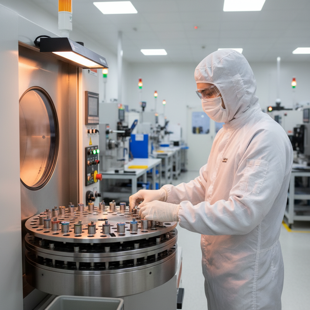
Sputtek operates multiple PVD systems and a Thermospray cell in Woodbridge (Regional Municipality of York), supported by in‑house blasting, cleaning, stripping, polishing, lapping, and a QC lab. High‑capacity SPUN systems handle prototype through large‑batch runs with repeatable adhesion and thickness control.
Our engineering-led team runs an integrated workflow: surface prep, PVD deposition, and post-processing under ISO 9001:2015 and Nuclear N299.3 approvals. This keeps variability low and turnaround predictable for regulated sectors.
- SPUN 2,000: High-capacity PVD coating system ideal for steady mid- to large-batch cycles and thicker builds.
- SPUN 4,000: Very high capacity (multi-thousand-kilogram per cycle class) for big, mixed tooling fleets.
- In-house processes: Sandblasting, microblasting, degreasing/cleaning, stripping, polishing, lapping, QC lab testing.
- Industries served: Automotive, aerospace, oil & gas, nuclear, defence, medical, pharmaceutical, and food & packaging.
Local considerations for Woodbridge
- Plan drop-offs and pickups around the Weston Rd / Highway 7 corridor to avoid rush windows and keep takt times smooth.
- Seasonal humidity swings can change incoming surface condition; request ion-etch adjustments during summer runs.
- For mixed production near SmartCentres Woodbridge suppliers, consolidate pre-/post-processing to minimize inter-facility handling.
Case Studies and Examples
Real production wins come from pairing the right PVD method with solid prep and QC. The examples below show 2–4× life gains, steadier finish, and fewer pulls across stamping, molding, machining, and component coating—delivered from Sputtek’s integrated Woodbridge operation.
Automotive Stamping: AlTiN via HiPIMS Sputter
- Challenge: Edge rounding and abrasive wear on high-strength steel blanks causing frequent re-sharpening.
- Action: Microblast + ion-etch; AlTiN with HiPIMS for dense film; controlled bias and 3 μm thickness.
- Result: ~3× interval between pulls; steadier burr height; reduced downtime and more predictable weekend shifts.
Plastic Injection Molding: DLC on Pins and Cores
- Challenge: Galling and sticking on resin-additive blends; part eject issues.
- Action: DLC at lower temperature with tight bias to preserve core temper; 1–2 μm target thickness.
- Result: Eject forces down; finish stabilized; scrap reduced; maintenance windows shortened.
Machining and Cutting: AlTiN/CrN Multilayer
- Challenge: Heat and crater wear in roughing operations on alloy steel.
- Action: AlTiN base for hot hardness; CrN top for lubricity; sputter with moderate bias and 2–3 μm build.
- Result: Tool life roughly doubled; more consistent chip control across batches.
Pharma Tooling: CrN Barrier on Tablet Punches
- Challenge: Corrosive additives pitting punch surfaces and raising scrap.
- Action: Fine polish + CrN sputter layer at 1–1.5 μm; strict cleaning and bake-out.
- Result: Surface pitting suppressed; finish held steady over longer runs; setup intervals extended.
Component Coating: Arc CrN on Sliding Pivot
- Challenge: Adhesive wear and fretting on a steel pivot under oscillating load.
- Action: Filtered arc CrN at 2–4 μm; post-polish to target Ra.
- Result: Wear scar width reduced; lubricant retention improved; maintenance interval increased.
PVD vs Thermospray (Pulsed HVOF)
Use PVD when you need thin, hard, low-friction films with tight dimensional control. Use Thermospray (Pulsed HVOF) for thicker builds, impact resistance, or dimensional restoration. Many fleets combine both—PVD for slip/wear surfaces, HVOF for bulk wear or corrosion layers.
PVD films are typically 1–10 μm and excel at friction and cutting wear. Thermospray coatings are tens to hundreds of microns and excel at impact/erosion resistance and dimensional build-up. Hybrid stacks (e.g., HVOF base + PVD topcoat) can blend properties for challenging duty cycles.
- Dimensional tolerance: PVD changes size minimally; ideal for sharpened dies and precision cores.
- Impact/erosion: HVOF wins for thickness and toughness; think pump shafts, valves, and restoration.
- Friction targets: DLC and nitride PVD families often reach 0.05–0.3 CoF; HVOF depends on material and finish.
If you’re comparing routes, it helps to review cross-industry examples like an automatic coating portfolio and process overviews of material method selection from adjacent disciplines such as polymer synthesis guides or method comparisons that illustrate trade-offs.
Frequently Asked Questions
These quick answers address the questions we hear most from engineers moving from trials to production. Each response is direct and production-focused to speed your decision-making and cut trial loops.
What are the main physical vapor deposition methods?
Sputtering (including magnetron and HiPIMS), cathodic arc (often filtered to reduce droplets), and evaporation with ion assistance (ion plating/IBAD) are the primary methods. Each balances ionization, rate, temperature, and coverage differently to target wear, friction, and corrosion goals.
When should I choose PVD over Thermospray (HVOF)?
Pick PVD for thin, hard, low-friction films with tight dimensional control (dies, molds, cutting tools). Choose HVOF when you need thicker builds for impact, erosion, or dimensional restoration. Hybrid stacks—HVOF base with a PVD topcoat—are common for severe duty.
How thick are PVD coatings and how long do they last?
Most production PVD films are 1–5 μm on tools and 0.5–3 μm on components. Life varies by load case and maintenance, but 2–4× service life improvements are common when prep, bias, temperature, and chemistry are in control and matched to the application.
Which PVD chemistry should I start with?
For hot cutting or abrasive wear, AlTiN or multilayers with CrN are solid starting points. For sliding and sticking issues in molding or components, DLC variants are often best. Always validate with pilot parts—thickness, hardness, adhesion, and friction—before scaling.
Key Takeaways
Match the PVD method to your substrate, geometry, and duty cycle; control prep, bias, and temperature; and verify every lot with coupons. Doing so prevents flaking, stabilizes finish, and often doubles service life while keeping takt times predictable.
- Use sputtering for smooth, uniform films; arc for maximum density and adhesion; ion-assisted evaporation for sensitive substrates.
- Keep gas ratios and bias tight; small drifts compound into soft films or microcracks in weeks.
- Measure thickness, hardness, and adhesion on every batch; trend base pressure and power to catch early drift.
- Leverage in-house prep and post-processing to cut variability and turnaround.
Conclusion
Physical vapor deposition methods give manufacturers a controllable, repeatable path to harder, slicker, longer-lasting surfaces—without sacrificing dimensional accuracy. With the right method and disciplined controls, you can reduce downtime, improve Cp/Cpk, and protect margins across stamping, molding, cutting, and component fleets.
Ready to shorten trial loops and stabilize your fleet? Talk with Sputtek’s engineering team at 110 Sharer Rd in Woodbridge. We support prototype to large-batch runs and help you decide when to use PVD alone or with Thermospray (Pulsed HVOF) for severe duty.