Diamond-like carbon (DLC) coating is a hard, low-friction carbon film deposited by PVD to reduce wear and extend component life. At 110 Sharer Rd in Woodbridge, our team at Sputtek applies diamond like carbon dlc coating on tools, dies, and precision parts to cut friction, resist abrasion, and stabilize performance in production.
By Ron — Sputtek • Last updated: 2026-06-16
Above the fold: hook + how to use this guide
This practical field guide shows what DLC is, why it matters, how PVD deposition works, and exactly when to specify it. You’ll get short answers, checklists, tables, and local context for Woodbridge manufacturers so you can move confidently from prototype to stable production runs.
Use this guide to move from curiosity to a confident specification. It’s written for manufacturing engineers, toolmakers, production leaders, QA, and procurement.
- What DLC coating is
- Why DLC matters in Woodbridge
- How PVD DLC works
- Types of DLC and uses
- DLC vs TiN/TiCN/CrN
- Best practices checklist
- Tools, systems, resources
- Case studies and examples
- FAQ
- Key takeaways
- Conclusion and next steps
Overview
DLC is a family of carbon coatings combining diamond-like hardness with graphite-like lubricity. In industrial use, DLC lowers friction (often to 0.05–0.15), raises surface hardness (commonly 2,000–4,000 HV), and protects against abrasive wear, adhesion, and scuffing under mixed or dry sliding.
Engineers choose DLC to stabilize uptime, tighten Cp/Cpk, and reduce scrap in stamping, cutting, molding, and component assemblies. Typical thicknesses are 1–3 μm, deposited at low temperatures compatible with many tool steels and non-ferrous alloys.
What is diamond-like carbon (DLC) coating?
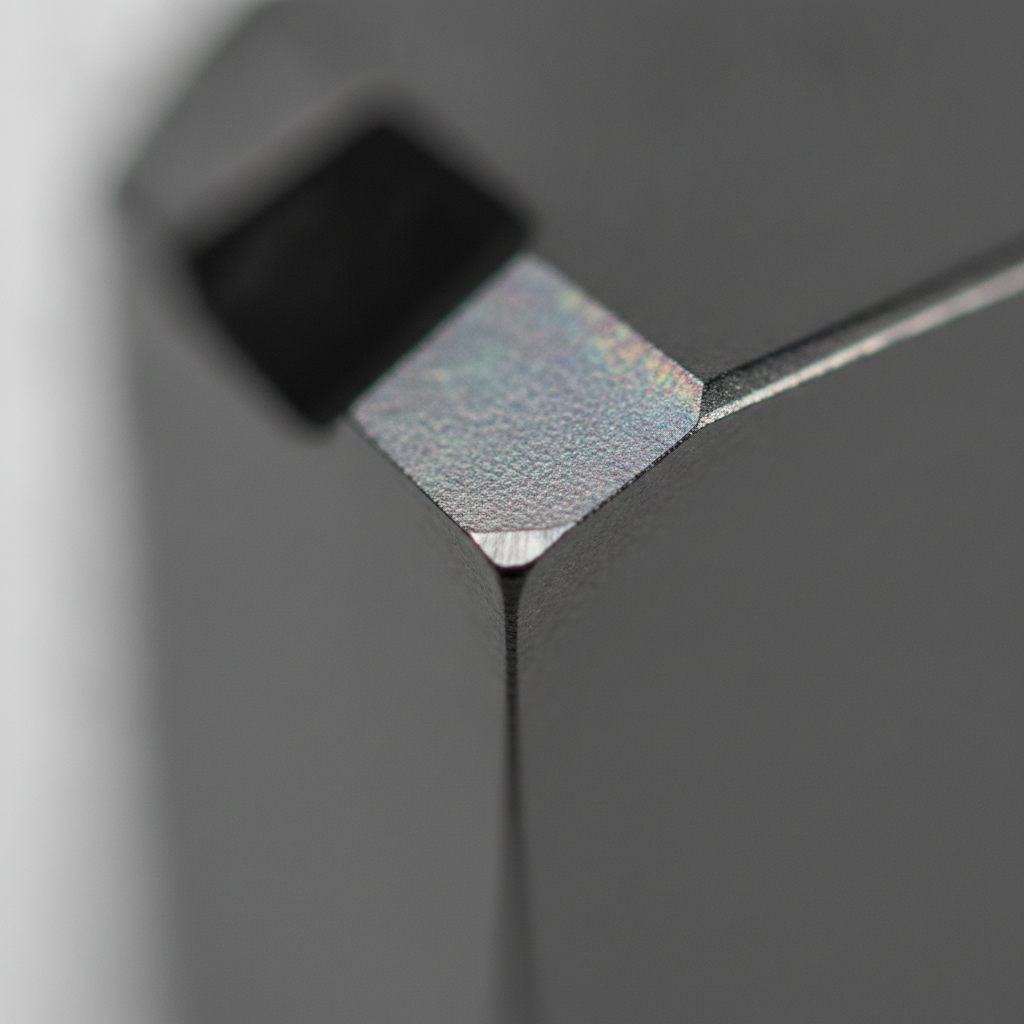
Diamond-like carbon is a thin, amorphous carbon film deposited by physical vapor deposition. It blends sp3 (diamond-like) and sp2 (graphite-like) bonding to deliver high hardness and very low friction, which reduces wear, galling, and stick-slip in demanding production environments.
DLC is not a single recipe; it’s a category. Variants range from hydrogenated a‑C:H films to hydrogen-free ta‑C and doped chemistries (e.g., W‑C:H) that tune stress, hardness, friction, and temperature stability. The practical outcome: smoother running interfaces, less adhesive wear, and more predictable tool life.
- Hardness and durability: DLC commonly reaches 2,000–4,000 HV. Hydrogen-free ta‑C can exceed that while maintaining a dense, glassy structure.
- Low friction: In boundary lubrication and dry contact, coefficients of 0.05–0.15 are typical, slashing heat and adhesive transfer.
- Conformal thin film: Typical thickness is 1–3 μm, thin enough to hold tolerances yet thick enough for protection.
- Low thermal budget: Many DLC processes run below 200–250°C, suitable for heat-sensitive substrates and tight-tolerance parts.
At Sputtek, we engineer DLC stacks to match your duty cycle—balancing adhesion, residual stress, and lubricity for the real-world loads your tools and components see on the line.
Why DLC matters for manufacturers in Woodbridge and the Regional Municipality of York
DLC matters locally because it protects high-throughput tools and components from galling, scuffing, and abrasion. In Woodbridge’s manufacturing corridor within the Regional Municipality of York, reducing unplanned downtime and stabilizing cycles directly protects capacity, quality, and on‑time delivery.
Here’s the reality: every unplanned die pull or tool change ripples through schedules, WIP, and customer commitments. DLC’s low friction and high hardness reduce pick-up on dies, minimize built-up edge on cutters, and help eject plastic parts more cleanly. That leads to steadier cycles, fewer adjustments, and cleaner capability data.
- Stamping: DLC reduces transfer of aluminum or stainless to tool faces, helping preserve draw quality and avoid orange peel or tearing.
- Machining/cutting: Edge adhesion drops, heat zones shrink, and edge stability improves—especially in gummy alloys and dry/semi-dry cuts.
- Plastic molding: DLC smooths flow and ejection on gates, cores, and slides, reducing drag lines and sticking at intricate features.
- Components: On pins, shafts, and valves, DLC mitigates fretting and start‑stop scuffing in mixed lubrication.
Because Sputtek operates at 110 Sharer Rd, our team supports quick trials, fast turnarounds, and repeatability—from prototype to large‑batch production—under ISO 9001:2015 and Nuclear N299.3 approvals.
How DLC coating works (PVD fundamentals)
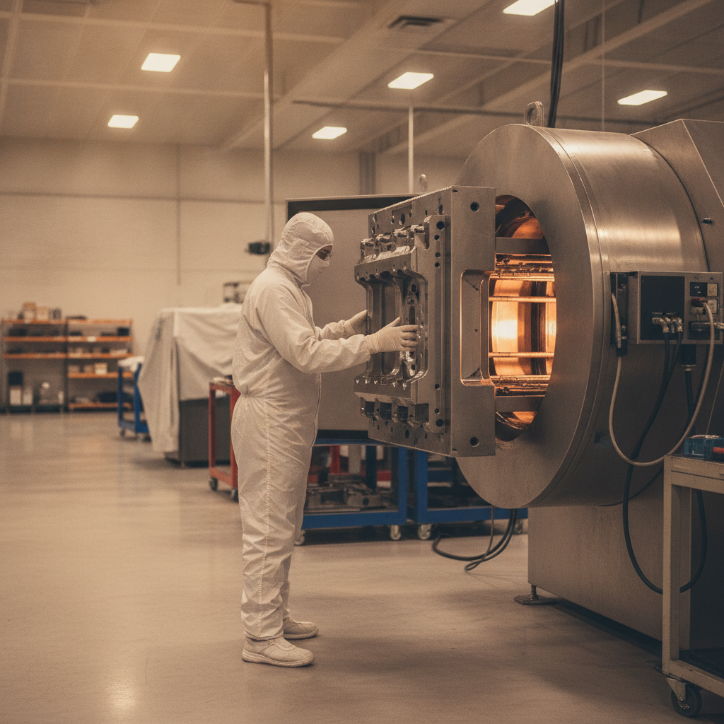
DLC is deposited in vacuum by PVD/PECVD processes. Hydrocarbon precursors ionize into a plasma; energetic carbon species condense on prepared parts to build a dense, adherent, low-friction film. Adhesion relies on surface prep, interlayers, bias, and controlled thermal budgets.
Any coating is only as good as the surface it bonds to. That’s why Sputtek runs end‑to‑end in‑house prep—sandblasting, microblasting, degreasing, and lapping—before chambering parts. Once under vacuum, we tune plasma energy, substrate bias, and hydrocarbon feed to lay down the desired DLC variant and thickness.
- Surface preparation: Cleanliness and roughness are tightly controlled to promote mechanical interlock and chemical bonding.
- Interlayers: Metallic or ceramic interlayers (e.g., Cr, Ti, Si) mediate stress, improve adhesion, and tailor thermal stability.
- Deposition control: Bias voltage, pressure, and gas chemistry steer sp3/sp2 content, residual stress, and tribology.
- Thermal management: Low process temperatures preserve substrates and dimensional accuracy.
For a deeper dive into deposition choices and when to use them, see our types of PVD deposition overview and our PVD sputtering best practices guide. We connect these fundamentals to real production constraints—fixture density, part geometry, and repeatability of coverage—so results scale.
Types of DLC and when to use each
DLC encompasses hydrogenated (a‑C:H), hydrogen‑free (ta‑C), and doped variants (e.g., W‑C:H). Each balances hardness, friction, stress, and temperature stability differently. Picking the right type requires matching contact mechanics, counterface materials, lubrication, and operating temperature.
a‑C:H (hydrogenated DLC)
- Profile: Low friction, good wear resistance, relatively lower residual stress; deposited at low temperatures.
- Use when: You need excellent lubricity under boundary/mixed regimes on steels, aluminum tooling, or polymer mold components.
- Typical numbers: 1–3 μm; friction 0.05–0.12 in dry sliding; hardness commonly 1,500–3,000 HV.
ta‑C (tetrahedral amorphous carbon, hydrogen‑free)
- Profile: Higher sp3 content, very high hardness and density; can tolerate higher contact stress; friction still low.
- Use when: You need maximum hardness and abrasion resistance on cutting edges, valve components, or high-load sliding.
- Typical numbers: 1–2 μm; hardness can exceed 4,000 HV; better stability at elevated temperature than a‑C:H.
Doped DLC (e.g., W‑C:H, Si‑DLC, N‑DLC)
- Profile: Dopants tune stress, adhesion, temp stability, and tribochemistry; tungsten‑doped types can improve load capacity.
- Use when: Counterfaces are harsh, loads are high, or temperatures approach limits; also to tune friction in specific lubricants.
- Typical numbers: Similar thickness; friction and hardness depend on dopant and stack design.
Stacked/graded architectures
- Profile: Adhesion interlayers, graded transitions, and topcoats manage stress and optimize run-in behavior.
- Use when: Geometry is complex, loads vary, or you need to balance ejection ease with abrasion resistance.
Choosing among these options is easier with a structured process. Our engineering team aligns tool steel, counterface, lubrication, and cycle data to recommend a coating stack that’s robust in production, not just in the lab.
DLC vs TiN, TiCN, CrN: how to choose for tools and dies
Use DLC for low friction and anti-galling in sticky alloys, molding, and mixed lubrication. Choose TiN/TiCN for balanced hardness/heat on ferrous cutting; pick CrN for corrosion resistance and thermal stability. The right pick depends on contact mechanics, heat, and counterface chemistry.
All coatings are trade-offs. DLC brings standout lubricity and adhesion control, but some nitride/oxy-nitride families maintain color, oxidation stability, or hot-hardness advantages at elevated temperatures. The table below summarizes practical tendencies engineers weigh when selecting a film.
| Property/Use | DLC | TiN | TiCN | CrN | Uncoated |
|---|---|---|---|---|---|
| Friction (dry) | Very low (0.05–0.15) | Moderate | Moderate–low | Moderate | High |
| Adhesive wear (galling) | Excellent | Good | Good | Good | Poor |
| Abrasion resistance | High (ta‑C highest) | High | Very high | High | Poor–moderate |
| Heat/oxidation tolerance | Moderate (type‑dependent) | Good | Good–very good | Very good | n/a |
| Corrosion resistance | Good | Fair | Fair | Very good | Poor |
| Great fits | Stamping non‑ferrous, molding ejectors, sliding parts | General cutting of steels | High‑speed/interrupted cutting | Hot molds, corrosive atmospheres | Low duty, non‑critical |
If you’re weighing finishes, our PVD types article and PVD finishing guide connect process physics to real production gains—reduced changeovers, better ejection, and cleaner edges.
Best practices for specifying and applying DLC
Define the interface and failure mode first; then match DLC type, thickness, interlayers, and finish. Control prep, mask critical fits, validate with small trials, and lock a repeatable recipe before scaling. Document loads, cycles, and lubricants to make results transferable.
Specification checklist (engineer + vendor)
- Operating regime: Dry, mixed, or boundary? Peak loads? Sliding speed? Temperature exposure?
- Counterface/contact: Alloy, hardness, finish, and geometry. Where does galling or abrasion occur?
- Substrate: Tool steel/HSS/carbide/aluminum/titanium; prior treatments; surface hardness after heat treat.
- Target outcomes: Longer life, lower changeovers, ejection improvement, or capability stabilization (Cp/Cpk targets).
- Coating recipe: DLC type, interlayer(s), thickness window, and final finish (Ra/Rz) for run‑in behavior.
- Measurement plan: Incoming/outgoing inspection, adhesion/wear checks, and traceability.
Application do’s
- Specify masking for bearing fits and seal lands.
- Target 1–3 μm unless analysis dictates otherwise; confirm dimensional stack‑ups.
- Define a finish range (e.g., Ra 0.05–0.2 μm) post‑coat lapping to balance lubricity and contact area.
- Start with a pilot lot on representative parts; run to failure to validate mechanisms.
- Lock a documented recipe (prep → interlayers → DLC → post‑process) before broad deployment.
Common pitfalls
- Skipping prep or sending contaminated parts; adhesion issues start there.
- Over‑thick films to “make it tough” that actually raise internal stress and spall.
- Assuming DLC fixes thermal softening; if heat is the failure mode, consider alternative stacks.
- Ignoring counterface chemistry; some lubricants and materials change tribofilm behavior.
Local considerations for Woodbridge
- Batch deliveries near SmartCentres Woodbridge are simple to coordinate with our in‑house prep and coating cells on the same campus.
- Seasonal humidity swings can shift run‑in behavior on stamping dies; we adjust finish windows and interlayers accordingly.
- For parts shuttled via Weston Rd / Highway 7, plan standard crate/fixture kits so repeat lots enter chambers consistently fixtured.
When you’re ready to lock a spec, our team can translate production data into a controlled recipe and PPAP‑ready documentation.
Need a DLC readiness check? We offer a quick, no‑obligation assessment to align failure modes with a coating stack and prep plan. You’ll get practical next steps for your tools or components.
Tools, systems, and resources
Effective DLC programs pair the right coating stack with reliable equipment, fixtures, and QC. Sputtek’s SPUN 2,000 and SPUN 4,000 PVD systems support scalable recipes, while in‑house labs verify adhesion, thickness, and finish before release to production.
We operate a modern 15,000 sq ft facility with multiple PVD machines and a Thermospray cell. High‑capacity SPUN systems (up to 3,000 kg/cycle) let us coat large batches consistently—critical for stable takt times and reliable turns.
- Systems: SPUN 2,000 and SPUN 4,000 for small to large runs; custom system design for unique parts/fixtures.
- Prep and post: In‑house sandblasting, microblasting, degreasing, stripping, and after‑coating lapping for tight Ra control.
- QC: Thickness mapping, adhesion checks, and surface finish verification with documented release criteria.
- Process documentation: Repeatable routes from prototype through PPAP and volume coating.
For foundational background on carbon as a material (consumer‑oriented but helpful for non‑technical stakeholders), you can review these primers on diamond fundamentals: an overview of the 4Cs of diamonds, a brief on diamond clarity, and a look at diamond carat basics. While jewelry‑focused, they help non‑engineers visualize hardness and structure concepts distinct from DLC.
For PVD fundamentals oriented to industrial outcomes, our internal resources connect directly to manufacturing realities: see types of PVD deposition, PVD sputtering best practices, and our PVD finishing guide.
Case studies and real‑world examples
DLC delivers when matched to the failure mode. In stamping, it curbs pick‑up; in molding, it helps ejection; in machining, it stabilizes edges under adhesion. The following mini‑scenarios mirror the issues we see—and solve—across automotive, aerospace, and medical tooling.
Automotive stamping: aluminum pick‑up on draw dies
- Problem: Adhesive wear on Class‑A aluminum panels caused frequent die wipes and re-polishing.
- Action: Prepped and applied a‑C:H DLC with a graded Cr interlayer; lapped to a tighter Ra window.
- Result: Noticeably cleaner runs; reduced wipe frequency; more stable surface quality through longer campaigns.
Plastic injection molding: ejector sticking on complex cores
- Problem: Sticking during ejection created drag lines and intermittent short shots on tight features.
- Action: DLC on gates, cores, and slides; targeted post‑coat polish on critical flow paths.
- Result: Smoother ejection; fewer interruptions; better repeatability of fill and finish across shifts.
Cutting tools: built‑up edge in gummy alloys
- Problem: Edge adhesion and heat softened HSS drills during semi‑dry operations.
- Action: ta‑C DLC stack for high hardness and low friction; fixture to maximize directional coverage on edges.
- Result: Cleaner chips; steadier edge; longer intervals between regrinds.
When scaling these wins, we validate coating thickness, adhesion, and finish on every lot. Because prep and post happen under one roof at 110 Sharer Rd, batches move from blasting to chamber to QC quickly and predictably.
FAQ: Diamond-Like Carbon (DLC) Coating
These concise answers address the DLC questions we hear most from engineers and buyers. Each response is direct and focused so you can move projects forward without sifting through jargon.
What problems does DLC coating solve?
DLC reduces friction and wear, so it’s ideal for stopping galling, scuffing, and abrasive wear on tools and components. In practice, it helps dies stay cleaner, cutters avoid built‑up edge, and mold tools eject parts more consistently.
How thick is a typical DLC coating?
Most industrial DLC films run 1–3 μm. That’s thin enough to maintain tolerances yet thick enough to add meaningful wear and adhesion protection. Thickness is tuned to geometry, load, and desired life between service intervals.
Can DLC be applied to aluminum tooling?
Yes. With the right interlayers and low‑temperature deposition, DLC works well on aluminum tooling, especially for anti‑galling and improved ejection in forming or molding. Proper surface prep and masking are essential for adhesion and fit.
Is DLC better than TiN or CrN?
It depends on the failure mode. DLC wins on lubricity and galling resistance. TiN/TiCN excel in many ferrous cutting operations, while CrN offers stronger corrosion and heat resistance. Match the coating to contact mechanics, heat, and counterface chemistry.
What industries benefit most from DLC?
Automotive stamping, machining and cutting, plastic injection molding, aerospace mechanisms, medical components, and food and packaging assemblies all benefit. Any application fighting friction, pick‑up, or abrasive wear is a strong candidate for diamond‑like carbon DLC coating.
Key takeaways
DLC is a practical lever for cutting friction, stabilizing cycles, and extending life on tools and precision components. Success hinges on clear failure‑mode definitions, disciplined prep, the right interlayers, and a repeatable recipe verified by QC at production scale.
- DLC is a family of films; pick a‑C:H, ta‑C, or doped variants to match loads and temperature.
- Most industrial programs target 1–3 μm, tight Ra/Rz, and robust interlayers for adhesion.
- Use DLC to fight galling in stamping, drag in molding, and built‑up edge in cutting.
- Lock a documented route from prototype to volume before broad rollout.
Conclusion and next steps
If you’re fighting galling, scuffing, or unpredictable edges, DLC is a proven fix. Start with a pilot on representative tools, validate the failure mode, and then standardize a recipe that scales from trials to volume with consistent prep and QC.
We help manufacturers translate line problems into coating solutions—from prototype through PPAP and large‑batch production. Explore our PVD finishing guide and automotive stamping overview to connect DLC decisions to real operational gains.
Ready to evaluate DLC on your parts? Book a discovery session at our Woodbridge facility (110 Sharer Rd). Our engineering team will review failure modes, recommend a coating stack, and outline a route to stable, repeatable results.


