Diamond-like carbon coating is a hard, low-friction carbon film deposited by PVD to protect tools and components from wear and galling. At 110 Sharer Rd in Woodbridge, Sputtek applies diamond-like carbon coating (DLC) on production tooling and precision parts to cut friction, extend tool life, and stabilize quality across demanding industries.
By Ron — Sputtek
Last updated: 2026-06-17
Quick Summary
DLC is a thin, carbon-based coating that combines high hardness with an ultra-low coefficient of friction. Applied by PVD at 150–300°C, it reduces wear, mitigates adhesion, and can improve uptime on tools and components. This guide explains what DLC is, how it’s deposited, and when to choose it.
Use this complete guide to understand DLC in practical terms and make confident decisions for production tooling and precision components.
- What DLC is and how it works in PVD systems
- When DLC outperforms TiN, TiAlN, and CrN
- Thickness, hardness, friction, and temperature limits to expect
- Best practices for surface prep, masking, and QC
- Real applications in stamping, molding, and cutting tools
- Local tips for Woodbridge and the Regional Municipality of York
What Is Diamond-Like Carbon Coating (DLC)?
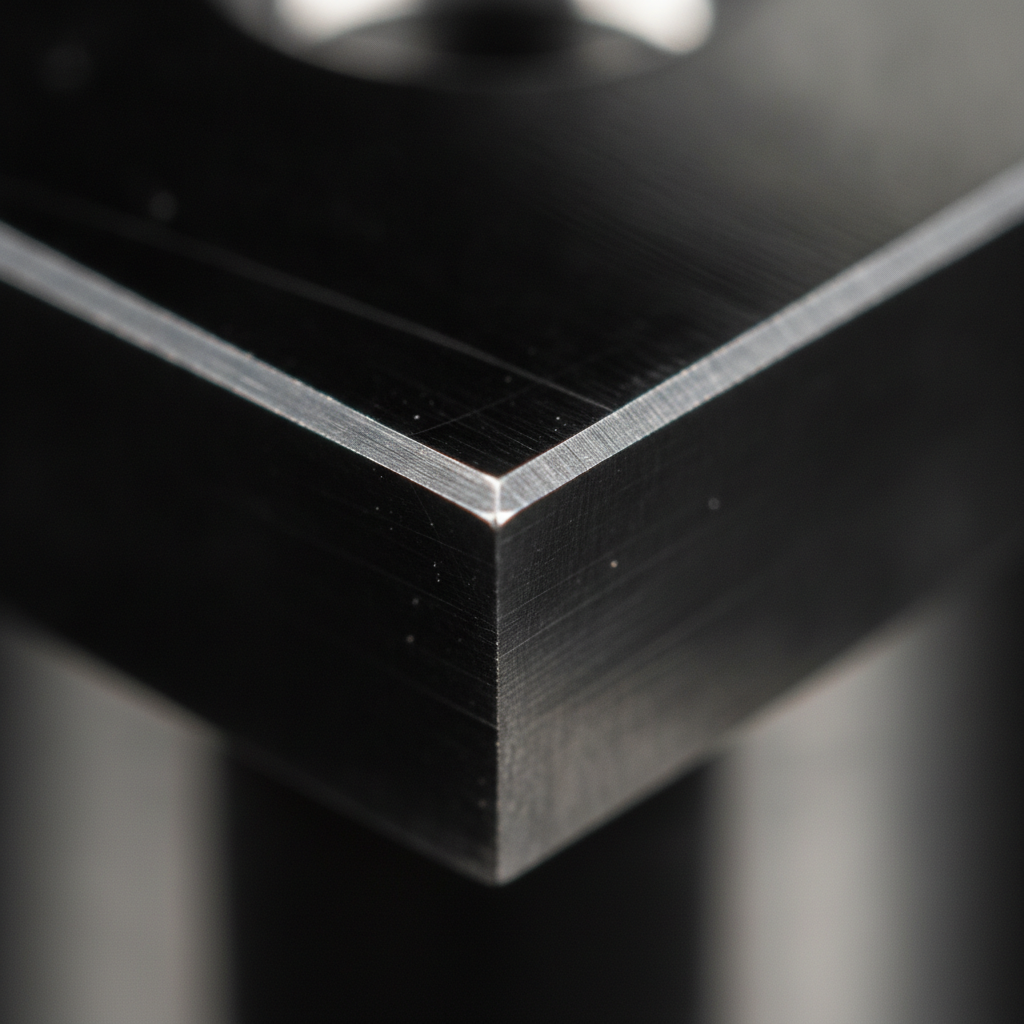
Diamond-like carbon (DLC) is a family of amorphous carbon films with significant sp3 bonding that deliver high hardness (often 1,200–3,000 HV) and very low friction (as low as ~0.05 against steel). Deposited as thin films (typically 1–4 µm), DLC protects tools and components from abrasive wear, adhesion, and scuffing.
In our experience, DLC behaves like a “slick armor” for metal surfaces. The film’s dense carbon network resists abrasion while its low shear promotes sliding instead of sticking. On stamped steel, for example, DLC can reduce pickup and galling at typical line speeds without changing the base tool geometry.
- Bonding structure: Amorphous carbon with mixed sp2/sp3; higher sp3 (e.g., ta-C) generally means higher hardness.
- Typical hardness: ~1,200–3,000 HV depending on DLC type and dopants.
- Coefficient of friction: Commonly 0.05–0.20 against steel under boundary lubrication.
- Film thickness: Often 1–4 µm; micro-features and sharp edges remain intact.
- Deposition temperature: Approx. 150–300°C, friendly to tempered tool steels and many substrates.
“Diamond-like” describes bonding and properties, not gemstones. It’s unrelated to consumer diamond grading like the 4Cs, certification, or clarity used in jewelry contexts (diamond 4Cs overview; diamond certification basics; diamond clarity reference).
Why DLC Matters for Production Performance
DLC lowers friction and resists wear, which stabilizes cycle times, reduces scrap, and extends tool service intervals. For many operations, those gains translate into fewer unplanned stops and more consistent parts per shift without retooling the process window.
Here’s the thing: friction, adhesion, and abrasion silently tax throughput. DLC directly targets those failure modes. In stamping, we routinely see cleaner draw surfaces and steadier dimensional control. In molding, ejector pins slide free more reliably, even as resin lots vary. On cutting tools, edge retention holds up longer, preserving surface finish.
- Less adhesive wear: The low shear surface cuts the tendency for workpiece material to stick and build up.
- Lower friction heat: Reduced µ curbs localized heating, helping coatings and substrates stay within temper limits.
- Stable dimensions: Thin films (microns) preserve tolerances and sharp edges, key for precision components.
- Predictable runs: When wear is slower and smoother, preventive maintenance can be scheduled with confidence.
At Sputtek’s 15,000 sq ft facility, we back these performance drivers with in-house prep and QC, so coatings arrive production-ready rather than lab-perfect but shop-fragile.
Local DLC Support in Woodbridge (Regional Municipality of York)
Sputtek provides DLC coating and PVD services in Woodbridge for manufacturers across the Regional Municipality of York. Local engineering support, rapid logistics to 110 Sharer Rd, and certified quality systems (ISO 9001:2015; Nuclear N299.3) keep production lines moving with fewer vendor handoffs.
Local proximity matters when a die sticks on Friday at 4 p.m. Our team can assess tooling, recommend a surface stack, and manage prep, coating, and post-process steps under one roof. Prototyping through volume batches is routine—our SPUN systems handle up to 3,000 kg per cycle, which supports large-format setups.
Local considerations for Woodbridge
- Plan drop-offs and pickups around traffic near Weston Rd / Highway 7 to keep urgent turns predictable.
- Schedule critical coating runs ahead of winter weather windows; humidity swings can influence handling and pack-out.
- Consolidate pre- and post-coat steps with us to minimize moves between facilities around SmartCentres Woodbridge.
How DLC Coating Works (PVD Fundamentals)
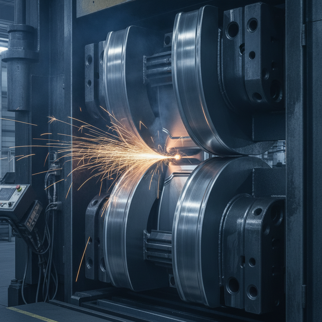
DLC is deposited in a vacuum PVD chamber where energetic carbon species condense onto clean, masked parts. Ion bombardment densifies the film and promotes adhesion. Careful control of plasma energy, bias, and gas chemistry tunes hardness, stress, friction, and color.
At a high level, DLC deposition follows a disciplined sequence. The gains you see on the floor start with consistency here. Below is a practical walk-through we use at Sputtek, adapted per substrate and geometry.
- Assessment and spec: Confirm substrate, prior treatments, target µ and hardness, thickness (often 2–3 µm), and operating temperature limits.
- Surface preparation: In-house degrease, microblast, and precision clean. Contamination control is non-negotiable for adhesion.
- Masking and fixturing: Define keep-out zones (e.g., threads, datum faces). Design fixtures for uniform line-of-sight coverage.
- Plasma clean/etch: Glow discharge to activate the surface and remove last monolayers of contamination.
- Nucleation/adhesion layer: Often a carbide/nitride interlayer (e.g., Cr, Ti) to bridge C film and substrate lattice behavior.
- DLC growth: Carbon-rich plasma builds 1–4 µm of film. Bias and gas mix (e.g., acetylene, argon) govern sp3/sp2 balance.
- Cool-down and inspection: Verify color, thickness (XRF), and adhesion (scratch, tape). Document lot records for traceability.
Typical deposition temperature remains in the 150–300°C band—friendly to many tool steels, carbides, and select stainless grades. That temperature window is a major reason DLC adapts well to legacy tooling without requalification of heat treatment.
Types of DLC and When to Use Them
DLC isn’t one material but a family: hydrogenated (a-C:H), tetrahedral (ta-C), metal-doped (Me-DLC), and doped variants (e.g., W-DLC, Si-DLC). Each balances hardness, internal stress, temperature ceiling, and friction behavior for specific applications.
Choosing the right variant is the lever that turns “good” into “great.” Below are simplified patterns we use to align coating chemistry with failure modes and operating conditions.
Common DLC variants
- a-C:H (hydrogenated DLC): Low friction, good for sliding contacts and adhesive wear control; moderate temperature ceiling.
- ta-C (tetrahedral DLC): High sp3 content, very hard and wear resistant; higher intrinsic stress; better at elevated temperatures than a-C:H.
- Me-DLC (metal-doped, e.g., W-DLC, Cr-DLC): Tailored stress and tribology; useful where mixed regimes or impact are present.
- Si-DLC / N-doped DLC: Adjusts bonding, improves thermal stability or chemical resistance for niche chemistries.
Rules of thumb
- Temperature limit: a-C:H often prefers ≤250–300°C service; ta-C can tolerate higher; for >400°C, consider TiAlN-family ceramics.
- Impact and load: For heavy impact, a tougher stack (e.g., Me-DLC with graded interlayer) can mitigate cracking.
- Lubrication state: In boundary/mixed lubrication, DLC’s µ shines; in high-temperature dry cutting, TiAlN usually wins.
- Substrate match: Adhesion and residual stress management depend on the steel/carbide grade and prior heat treatment.
We routinely specify a DLC stack with a tailored interlayer and 2–3 µm top film for sliding tool components, while opting for TiAlN on cutters that see red heat and chip loads.
DLC vs TiN, TiAlN, and CrN: Practical Comparison
Use DLC when you need low friction and anti-adhesion at modest temperatures. Choose TiAlN when heat resistance matters most. CrN offers balanced wear and corrosion resistance. TiN is versatile and visual but usually higher friction than DLC.
| Property | DLC | TiN | TiAlN | CrN |
|---|---|---|---|---|
| Typical hardness | ~1,200–3,000 HV | ~1,800–2,100 HV | ~2,500–3,500 HV | ~1,800–2,300 HV |
| Friction (steel) | ~0.05–0.20 | ~0.4–0.6 | ~0.4–0.6 | ~0.3–0.5 |
| Heat resistance | Good to moderate | Moderate | Excellent (high heat) | Good |
| Corrosion resistance | Good (chemistry-dependent) | Fair | Fair to good | Good to excellent |
| Color/appearance | Black/graphitic sheen | Gold | Purple/gray | Silver-gray |
| Best for | Sliding, anti-galling | General tool wear | High-temp cutting | Corrosive, impact |
These bands describe typical behavior. We often combine a nitrided substrate, a carbide/nitride interlayer, and a DLC top to balance adhesion and stress—especially on complex dies and form tooling.
Applications and Real-World Examples
DLC shines where sticking, sliding, and micro-abrasion dominate. We see strong gains on stamping dies, plastic mold components, precision wear parts, and select cutting tools that operate below red heat.
Consider these common scenarios we support from Woodbridge:
- Automotive stamping: Draw dies and trim edges run cleaner with less pickup on galvanized and AHSS; dimensional drift slows as surfaces stay smooth.
- Plastic injection molds: Ejector pins, slides, and cores eject more reliably; DLC’s low µ reduces scuffing on filled resins.
- Cutting tools: DLC-coated carbide routers in aluminum cutting can hold a shinier finish longer under boundary lubrication.
- Medical/pharma components: Valves and plungers benefit from low friction interfaces that reduce stick-slip.
- Packaging lines: Wear pads and guides last longer with fewer product scuffs and jams.
Because film thickness is microns, hole diameters, edge radii, and datum faces stay within tight tolerances—a crucial requirement across regulated sectors we serve.
Best Practices for DLC Success
DLC succeeds when cleanliness, fixturing, and interlayer design are right. Define targets, prep meticulously, mask precisely, and validate with thickness and adhesion tests. Small steps upstream prevent big headaches downstream.
Preparation and masking
- Specify the functional surfaces and keep-out zones clearly on prints.
- Use in-house degreasing and microblasting to hit cleanliness targets before vacuum load.
- Design fixtures for visibility and uniform film growth, avoiding deep shadowing.
Interlayers and stress control
- Select interlayers (Cr, Ti, or graded carbides/nitrides) to bridge C film and substrate behavior.
- Balance sp3 content with film stress to avoid edge cracking on sharp features.
- Target 1–4 µm thickness for most tooling to preserve dimensions yet deliver life extension.
Quality checks
- Measure thickness by XRF; verify uniformity across critical features.
- Confirm adhesion via scratch/tape tests appropriate to geometry.
- Document lot IDs, parameters, and results for traceability.
Our end-to-end in-house steps—sandblasting, microblasting, cleaning, stripping, lapping, and QC lab work—simplify this workflow so customers don’t juggle multiple vendors mid-project.
Tools, Systems, and Resources
High-capacity PVD systems and disciplined QC convert coating theory into production results. Sputtek’s SPUN 2,000 and SPUN 4,000 platforms handle large batches consistently, while our lab and finishing stations ensure coatings meet spec out of the chamber.
- SPUN 2,000: Up to ~1,200 kg per cycle—ideal for mid-to-large runs and complex fixturing.
- SPUN 4,000: Up to ~3,000 kg per cycle—built for large-format and high-volume throughput.
- Thermospray cell (Pulsed HVOF): For parts needing thermal spray coatings instead of or in addition to PVD films.
- QC Laboratory: Thickness, adhesion, and finish verification to customer and regulatory requirements.
For a deeper dive into deposition options and finishing, explore our PVD types overview and our PVD finishing guide. For sputtering fundamentals, see our sputtering guide.
Step-by-Step DLC Implementation Checklist
Define targets, prepare parts, plan masking/fixturing, validate the stack, and document QC. A simple, consistent checklist reduces misses and rework, especially when scaling from prototypes to batch production.
- Define coating goals (µ, thickness, color, temp).
- Confirm substrate grade and heat treat; note any brazes/inserts.
- Mark keep-outs; provide models for fixture design.
- Approve interlayer + DLC stack proposal.
- Run pilot pieces; measure thickness/adhesion.
- Release production batch; record chamber parameters.
- Post-process (if needed): polish/lap to finish spec.
- Install and monitor; capture tool-life/quality data.
Case Studies and Practical Wins
Across stamping, molding, and precision components, DLC often delays the onset of adhesion and micro-abrasion. The result is steadier quality and fewer emergency pulls. Below are brief, anonymized snapshots from recent work.
- Automotive stamper (GTA): Trim edges on galvanized steel showed smoother edges for longer intervals; line stoppages for cleaning dropped after a DLC stack with a carbide interlayer.
- Medical device tooling: Ejector pins with tailored a-C:H maintained consistent eject forces across resin lot changes, improving dimensional stability on a critical feature.
- Aluminum cutting: DLC on carbide routers improved surface shine on 6xxx series parts under mist lubrication; measured finish held tighter over extended footage.
These results reflect the core DLC advantage: thin, slick, durable films that protect without changing geometry. For high-heat cutters, we routinely recommend TiAlN instead—right tool, right job.
Frequently Asked Questions
These concise answers address common buyer and engineering questions about DLC. Each response assumes production realities: mixed materials, time pressure, and strict tolerances.
What is the typical DLC thickness for tooling?
Most tooling runs 1–4 µm to preserve dimensions while adding wear resistance. We commonly target 2–3 µm for sliding components and adjust based on geometry, substrate, and desired service interval.
When is DLC better than TiAlN?
Choose DLC for low friction and anti-adhesion at modest temperatures—stamping, molding components, wear parts, and aluminum machining. Pick TiAlN for high-heat cutting where oxidation resistance and hot hardness dominate.
Can DLC be applied to stainless steel and carbide?
Yes. With the right interlayers and surface prep, DLC adheres well to many tool steels, stainless grades, and carbides. We validate adhesion with scratch/tape tests and monitor thickness by XRF on critical features.
Does DLC change part dimensions?
Only by microns. Films are typically 1–4 µm, so sharp edges and tolerances remain intact. When faces must stay bare, we mask those zones and verify film on the functional surfaces only.
Key Takeaways
DLC is a thin, hard, low-friction carbon film applied by PVD at moderate temperatures. It curbs wear and adhesion without shifting part geometry—ideal for stamping, molding components, and select cutting tools below red heat.
- DLC reduces friction to ~0.05–0.20 against steel and resists adhesive wear.
- Typical thickness is 1–4 µm; hardness often 1,200–3,000 HV depending on type.
- Pair the right interlayer and DLC variant to match load, temp, and substrate.
- Use TiAlN-family ceramics for high-temperature cutting applications.
- End-to-end in-house prep and QC simplify reliable production outcomes.
Conclusion and Next Steps
If sticking, scuffing, or micro-abrasion are hurting uptime, DLC is a proven lever. With careful prep, fixturing, and the right interlayer, you can stabilize output without redesigning tools or components.
Ready to evaluate a part? Start with a small pilot, define µ and thickness goals, and capture before/after tool-life and quality metrics. For context on deposition families and finishing paths, see our guide to PVD types and our finishing best practices. Terminology note: DLC is not related to gemstone grading—see this consumer 4Cs explainer for that separate topic.
Talk with an engineer: If you’re in Woodbridge or the GTA, our team at 110 Sharer Rd can review your tooling, recommend a coating stack, and coordinate prep-to-QC under ISO 9001:2015 and Nuclear N299.3 systems. Request a DLC review.
Not to be confused with diamond jewelry terminology (4Cs, clarity, certification). For that consumer context, see this certification primer and a brief clarity reference.
Want to get deeper into deposition science? Our sputtering fundamentals article pairs well with this guide, and our automotive stamping overview connects coating selection to real press-line constraints.


