
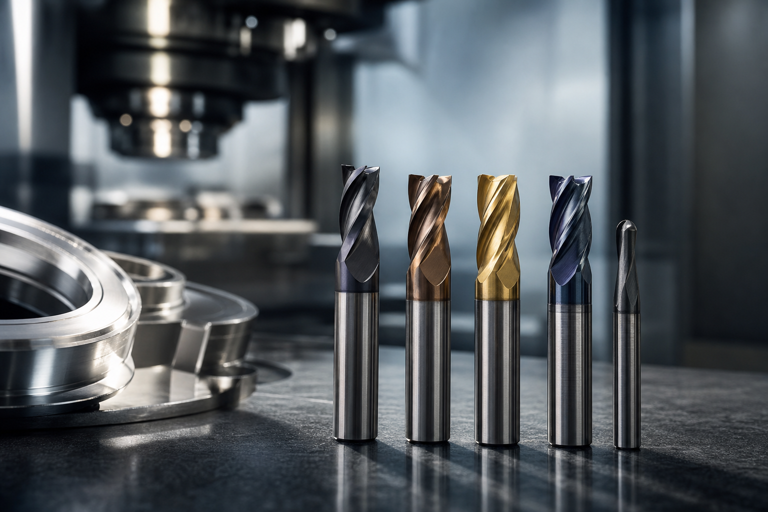
How to approach cutting tool coating selection
Choosing the right cutting tool coating starts with the workpiece material and the cutting mode, then narrows to coating family, tool substrate, and a controlled pilot plan. This article gives a reproducible, ordered workflow you can use at the engineering desk and in an RFQ: a quick checklist, decision rules for common coatings, post-coating parameter changes, pilot acceptance gates, and a vendor prequalification checklist tailored to prototype-to-volume production in regulated sectors.
Quick decision checklist
Use this checklist to capture the minimum data you must have before shortlisting coatings or vendors. Capture these five items for every tool and job.
- Workpiece material and temper, for example AISI 1045 annealed, 304 stainless, or 7075-T6 aluminum.
- Cutting mode and objective: roughing, finishing, high-feed, or interrupted cuts.
- Tool substrate and heat sensitivity: carbide, ceramic, cermet, or HSS.
- Lubrication and adhesion risk: dry, flood coolant, cryogenic, or observed chip welding.
- Target run length and acceptable tool-life handoff for production, for example cycles before scheduled replacement.
Start with the material you are cutting because it dictates hardness, heat resistance, and lubricity requirements. The MSC Industrial guide on coating matching describes this as the most reliable first filter when choosing coatings.
How to use it in an RFQ: include the checklist values on each sample line, request recommended coating families, expected feeds and speeds adjustments, and ask for pilot-run acceptance criteria.
Step 1: Identify the workpiece and cutting conditions
Collect details that materially change coating choice. Use the following material notes as rules of thumb, then refine with application testing.
Ferrous steels and alloy steels
For medium to high carbon steels, coatings that offer wear resistance and moderate hot hardness perform well. Expect higher cutting temperatures under high-speed machining, so prefer coatings with good thermal stability.
Stainless steels and nickel alloys
These alloys cause heavy built-up edge and chemical adhesion. Coatings with strong hot hardness, for example TiAlN and AlTiN families, and a low chemical affinity reduce adhesion. Coolant strategy and surface finish also matter.
Cast iron
Cast iron is abrasive but less prone to built-up edge. Thick, hard coatings or CVD options can extend tool life under heavy abrasive wear conditions.
Aluminum and other non-ferrous metals
Aluminum tends to chip weld to tools. Low-friction coatings such as DLC are often the best starting point to reduce built-up edge and improve surface finish in dry or light-lubrication conditions.
Plastics and composites
For plastics and composites, low adhesion is the primary requirement. DLC or specialized low-stick PVD layers reduce polymer smearing and fiber pullout.
Surface condition and existing coatings on the workpiece
If the workpiece has surface treatments such as hard coatings, plating, or paint, note that a change in chemistry or abrasive inclusions may require alternate coatings or modified cutting parameters.
Tool performance depends first on tool material, coating, and geometry. A poor match among these causes chatter, heat, burrs, and early failure, a principle summarized in cutting-tools selection guidance.
Step 2: Match coating families to materials and failure modes
Below are practical mappings and the failure modes they address. Treat them as starting points for pilot trials rather than absolute rules.
TiN and TiCN, low-friction general purpose
- Best for mild steels and finishing operations where low friction improves surface finish.
- Limitations: lower hot hardness than TiAlN, so not ideal for high-temperature stainless machining.
TiAlN and AlTiN, hot hardness for stainless and high-speed applications
- Strong hot hardness and oxidation resistance, useful for stainless steels and high-speed dry cutting.
- Trade-off: higher cutting temperatures, so verify tool substrate thermal limits and adjust speeds accordingly.
DLC coatings, low friction and non-stick
- Excellent for aluminum and polymer composites where chip welding and adhesion are dominant failure modes.
- DLC is chemically dissimilar to aluminum, which reduces built-up edge. The general rule to avoid coating chemistries similar to the workpiece reduces adhesion and diffusion wear.
CVD coatings, thick high-temperature resistance for abrasive steels
- CVD layers are typically thicker and more abrasion resistant, suited to long runs on highly abrasive steels. They require attention to geometry and substrate strength because of thickness and residual stress.
PVD variants and multilayers
- PVD offers thinner, tougher multilayers such as TiN/TiCN/TiAlN stacks with good adhesion and less dimensional change. Use PVD when tight geometry and edge sharpness matter.
Pulsed HVOF and thermospray, when thermal spray is preferred
Use thermal spray or pulsed HVOF for parts requiring very thick wear layers or when reconditioning heavy tooling where a thicker, tougher build is needed. Thermal spray is not a substitute for thin, high-precision PVD finishes on fine cutting edges, and should be treated as complementary for heavy-wear regimes.
For reference charts that compare heat limits, chip-welding risk, and recommended feeds and speeds, consult coating comparison tables when estimating thermal limits and starting parameters.
Step 3: Tool substrate and adhesion considerations
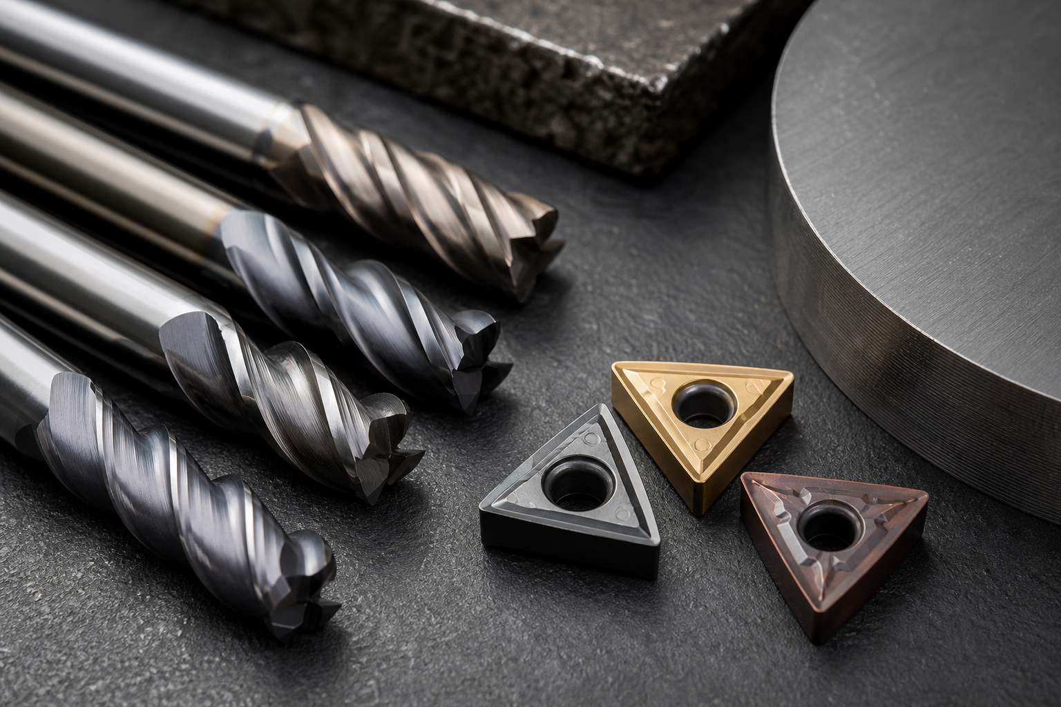
Coating choice must align with substrate and preparation methods because adhesion failures typically begin at the interface.
Carbide, ceramic, and cermet substrates
Carbide substrates are the most common recipients for PVD and work well with multilayer PVD. Ceramic substrates tolerate higher temperatures but are brittle and require coatings that do not increase chipping risk.
When to specify interlayers or adhesion-promoting pretreatments
Interlayers, graded stacks, or thin adhesion layers reduce delamination risk. Specify interlayers when switching to a coating family with different thermal expansion, or when recoating worn geometries.
Surface prep and blasting, why in-house prep matters
Repeatable surface prep such as sandblasting, microblasting, and degreasing reduces adhesion variability. Working with a vendor that performs these steps in-house improves traceability and reduces package-handling defects.
Step 4: Post-coating adjustments, feeds, speeds, and tool-life handoff
After coating, do not assume unchanged cutting parameters. Use a controlled ramp to find the new stable operating window.
How to run a controlled parameter ramp
- Start at conservative speeds and feeds specified by the coating vendor for the substrate and material.
- Increase speed in 5 to 10 percent steps while monitoring flank wear and surface finish.
- Hold each change for a representative number of cuts or time to observe cumulative wear rather than one-off results.
Common starting points and monitoring metrics
- Monitor flank wear, crater depth, surface roughness, chip form, and cycle time.
- Use a tool-life handoff: define a limit such as a VB flank-wear threshold or a surface roughness spec that triggers tool change in production.
Refer to coating comparison tables to estimate heat limits and likely chip-welding risk before running the ramp.
Step 5: Pilot testing, failure-mode checks, and scale acceptance criteria
Design a pilot that gives repeatable evidence for production scaling. A robust pilot reduces surprises during ramp-up.
Design a pilot
- Use representative parts or coupons and run the pilot under the same fixturing and cycle time as production.
- Include at least three repeat tools per geometry to capture process variation before scaling.
Measurements to collect
Record flank wear, crater wear, surface finish, cycle time, scrap rate, and chip form at preplanned intervals. Capture environmental and coolant conditions.
Failure-mode checklist
- Adhesion or delamination.
- Built-up edge and chip welding.
- Diffusion wear or chemical attack at elevated temperatures.
- Edge chipping and thermal cracking.
Move to production only after meeting acceptance gates you agree on with the coating vendor. Involve the vendor’s R&D for process tuning if failures point to chemistry or process limits.
Step 6: Vendor prequalification checklist and what to expect from a Toronto PVD partner

Procurement and engineering must evaluate technical and commercial readiness. Include these checks in vendor prequalification.
Mandatory technical checks
- Quality system certification and traceability, for example ISO 9001:2015, and any industry-specific approvals required for regulated parts. For nuclear work, confirm vendor-level approvals and traceability procedures.
- In-house surface preparation and post-processing such as sandblasting, microblasting, degreasing, stripping, polishing, and lapping. In-house services shorten turnaround and improve repeatability.
- Quality control laboratory capability: profilometry, adhesion tests, microscopic wear measurement, and batch-level reporting.
For local Toronto and Greater Toronto Area partners, confirm facility scale and equipment. For example, Sputtek describes a modern 15,000 square foot facility with PVD and Thermospray including Pulsed HVOF capabilities, in-house prep and QC, and high-capacity SPUN systems for batch consistency. These are the types of items you should verify in supplier responses.
Process and capacity checks
- Ask for recommended batch sizes, maximum tool dimensions per cycle, and typical lead times for pilot versus production batches.
- Verify coating systems and whether the vendor can scale from prototypes to thousands of parts without process drift; request process control records from prior runs where possible.
Service and commercial items
- Coating specification sheets, sample reports, and pilot pricing.
- Turnaround service level expectations for pilot and production, rework policies, and warranty or acceptance statements.
For a local service example and to learn what a Toronto PVD partner may offer for cutting tool coating work, review the supplier page dedicated to tooling: Tool Coating in Woodbridge: Cut Wear with Better Layers.
Common objections, trade-offs, and final decision criteria
Engineers commonly ask whether DLC, PVD, CVD, or thermal spray is best. Use this decision rule: pick the technology that solves the dominant failure mode with the smallest secondary trade-offs. DLC is appropriate for adhesion and aluminum, TiAlN for hot hardness on stainless, CVD for long-run abrasion, and pulsed HVOF for thick wear builds. Avoid coatings whose chemistry matches the workpiece to reduce built-up edge and diffusion wear, as advised by coating selection guidance.
FAQ
How do I choose between PVD, CVD, DLC, and thermal spray for a given workpiece material?
Choose the family that addresses the dominant failure mode. Use PVD for thin, precise multilayers and tight geometries. Use CVD for thick, abrasion-resistant finishes on steel. Use DLC for non-stick, low-friction needs on aluminum and polymers. Use pulsed HVOF or thermospray for thick, restorative or heavy-wear applications.
What tests should I run during a coating pilot to decide if I can scale to production?
Run representative cuts and measure flank wear, crater, surface finish, chip form, cycle time, and scrap rate. Include adhesion checks and a short accelerated wear sequence to reveal diffusion or delamination risks.
How should feeds and speeds change after applying a hot-hardness coating such as TiAlN or AlTiN?
Use a controlled ramp. Start conservatively, then increase cutting speed in small increments while monitoring wear. Hot-hardness coatings usually allow higher speeds but raise workpiece temperature, so confirm substrate tolerance before maximizing speeds.
What vendor certifications and in-house services matter for suppliers serving regulated industries?
ISO 9001:2015 certification is a baseline. For nuclear, medical, or aerospace work, confirm industry-specific approvals, traceability, in-house preparation and QC laboratories, and documented process controls.
How do I avoid built-up edge and poor adhesion when machining aluminum and stainless steel?
For aluminum, choose low-friction coatings like DLC and verify coolant and geometry to keep chips evacuating. For stainless and nickel alloys, use hot-hardness coatings such as TiAlN and AlTiN and consider lubricant strategy. Also avoid coating chemistries that include elements similar to the workpiece, which can increase adhesion and diffusion wear.
Key takeaway: follow a repeatable workflow. Capture material and cutting mode, match coating family to the dominant failure mode, confirm substrate and preparation, run a controlled pilot, and prequalify vendors on technical and capacity criteria before scaling.