Physical vapor deposition equipment is the integrated suite of vacuum chambers, power supplies, plasma sources, fixturing, and controls used to deposit thin, hard, and adherent coatings on tools and components. These systems operate under high vacuum with controlled energy to create dense films for wear, friction, and corrosion performance. For Woodbridge manufacturers, the right system stabilizes quality and throughput.
By Ron at Sputtek • Last updated: 2026-07-03
Summary
This guide explains what physical vapor deposition equipment includes, how it works, and which configuration best matches your parts, coatings, and volumes. You’ll see real examples from Sputtek’s SPUN series, a checklist for selection, a commissioning playbook, and maintenance tips built for high-volume manufacturing.
Here’s what you’ll learn in a few minutes of focused reading:
- What a modern PVD system is, and why it matters for uptime and repeatability
- Arc evaporation vs magnetron sputtering vs HiPIMS vs hybrid cells
- Core components: vacuum, power, gas, plasma sources, rotation/fixturing
- How to match equipment to substrates, part geometry, and batch size
- Commissioning, run recipes, maintenance, and quality control routines
- Case-backed examples from Sputtek’s ISO 9001:2015 operation in Woodbridge
Above-Fold Hook + TOC
If you’re evaluating PVD equipment, start with geometry, throughput, and coating family. Those three choices narrow power architecture, chamber volume, and fixturing. Use our quick table of contents to jump to the right section and build a practical, purchase-ready shortlist.
Use this table of contents to jump to what you need:
- What Is PVD Equipment?
- Why PVD Equipment Matters
- How Physical Vapor Deposition Works
- Types of PVD Systems and Methods
- Core Components and Key Specifications
- Selection Criteria: Matching System to Parts
- Installation and Commissioning Playbook
- Operations, Maintenance, and Uptime
- Quality, Metrology, and Process Control
- Case Studies and Practical Examples
- Tools and Resources
- Frequently Asked Questions
- Conclusion and Next Steps
What Is PVD Equipment?
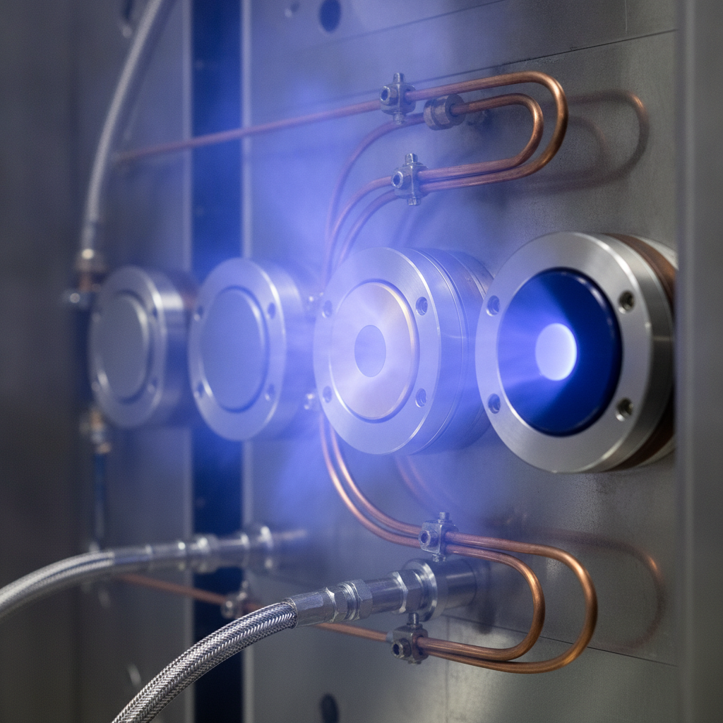
A PVD system is a controlled vacuum environment where a solid source (target/cathode) is vaporized and condensed onto parts as a thin, hard film. Equipment includes the chamber, pumps, gas delivery, power supplies, plasma sources, thermal management, motion/rotation, and software to repeat recipes safely and consistently.
In practice, physical vapor deposition equipment converts energy and gas chemistry into high-adhesion films. Typical coating thickness ranges from 1–5 microns, with multilayers or nanolaminates for advanced wear and friction control. Film density, stress, and adhesion depend on power mode, bias, gas ratios, and surface prep.
- Chamber scale: From small R&D cells to high-capacity systems supporting 1,200–3,000 kg per cycle (as in Sputtek’s SPUN series).
- Process families: Arc evaporation, magnetron sputtering, HiPIMS, and hybrid cells cover nitrides, carbides, oxides, and DLC.
- Applications: Stamping dies, plastic injection molds, cutting tools, aluminum die cast cores, and functional components.
For context, Sputtek operates multiple production PVD machines within a 15,000 sq ft facility, plus a Thermospray cell. That scale lets us tune recipes on prototypes and lock results for high-volume batches without changing hardware midstream.
To go deeper on deposition fundamentals, see our Woodbridge-focused overview of thin films in PVD coating in Woodbridge.
Why PVD Equipment Matters
The right PVD equipment stabilizes wear life, reduces friction, and improves first-pass yield. Reliable chambers, bias power, and motion deliver uniform thickness on complex parts, cutting scrap and unplanned downtime. Scalable systems also keep cycle cadence steady as volumes grow.
Here’s why this matters to manufacturing engineers and toolrooms:
- Tool life extension: Dense films with good adhesion delay edge rounding and galling. That means fewer tool pulls and more stable Cp/Cpk over time.
- Lower friction = cleaner parts: DLC and low-friction nitrides help parts release faster in molding and reduce pickup in stamping.
- Uniformity on geometry: Correct rotation, fixturing, and plasma density give even coverage over sharp features, IDs/ODs, and long aspect ratios.
- Regulatory confidence: ISO 9001:2015 and Nuclear N299.3 frameworks align traceability, calibration, and recipe control with OEM requirements.
- Throughput and predictability: High-capacity systems (up to 3,000 kg per cycle) synchronize with upstream/downstream takt.
We see this on the floor: when fixturing aligns with plasma exposure and bias, coating runs become repeatable, and the SPC charts stop wandering. The outcome isn’t abstract—it shows up as steadier die performance, cleaner molded parts, and fewer unplanned maintenance events.
For finishing options that balance wear and appearance, our short primer on PVD plating helps teams frame tradeoffs.
How Physical Vapor Deposition Works
PVD releases atoms from a solid source via arc evaporation or sputtering, transports them through a controlled vacuum/gas plasma, and condenses them on parts as a thin, engineered film. Adhesion depends on clean surfaces, energetic ion bombardment, and substrate bias during growth.
Key stages in every run:
- Prep and load: Degreasing, blasting/microblasting, and masking define adhesion; parts are racked with line-of-sight in mind.
- Pumpdown and heat: Vacuum evacuation (to the 10-3–10-6 Torr range) and soak set up a clean, thermally stable surface.
- Plasma clean/etch: Argon (and sometimes reactive) plasma removes residuals and activates the surface.
- Deposition: Arc or sputter sources evaporate the target; reactive gases form compounds like TiN, AlTiN, CrN, or DLC variants.
- Cool and vent: Controlled cooldown limits stress; venting protects fresh films from condensation.
Typical film families and context:
- Nitrides/carbides (e.g., TiN, TiCN, AlTiN): High hardness and hot hardness for cutting, stamping, and forming.
- Chromium-based (e.g., CrN): Better ductility and corrosion resistance for molds and components.
- DLC: Ultra-low friction and non-stick behavior for sliding or release-critical applications.
For a practical DLC perspective from pre-clean to post-process, scan our DLC coating process walkthrough and the complete DLC coating guide.
Types of PVD Systems and Methods
PVD methods include arc evaporation, magnetron sputtering, HiPIMS, and hybrid systems. Arc excels in deposition rate and hardness; sputtering delivers smooth, low-droplet films; HiPIMS adds dense microstructure and adhesion. Hybrids combine sources to balance rate, density, and finish.
Common PVD methods
- Arc evaporation: Cathodic arc spots eject ions at high rate—great for hard nitrides and carbides; watch for macro-particles on cosmetic surfaces.
- DC/RF magnetron sputtering: Lower droplet count and smoother films; ideal for molds, medical components, and decorative-functional finishes.
- HiPIMS (high power impulse magnetron sputtering): Pulsed, high-peak power increases ionization for denser films and improved step coverage.
- Hybrid cells: Combine arc cathodes and magnetrons for rate + smoothness on mixed-geometry racks.
When to choose which
- High-wear cutting tools: Arc or hybrid AlTiN/TiAlN for hot hardness; add bias for adhesion on tough substrates.
- Molds and cores with fine texture: Sputtered CrN or DLC to preserve surface finish and aid release.
- Mixed batches: Hybrid chambers maintain throughput without sacrificing finish on sensitive parts.
| Method | Strengths | Typical Coatings | Best For | Watchouts |
|---|---|---|---|---|
| Arc evaporation | Very high rate, hard films | AlTiN, TiCN, TiN | Cutting, stamping | Macro-particles on Class-A surfaces |
| Magnetron sputtering | Smoother finish, low droplets | CrN, TiN, DLC underlayers | Molds, components | Rate typically lower than arc |
| HiPIMS | Dense microstructure, adhesion | Advanced nitrides/oxynitrides | Complex geometry | Pulse power management |
| Hybrid | Balanced rate + finish | Stacked multilayers | Mixed part families | More complex sequencing |
For stainless finishes plus durability, explore the nuances in PVD stainless steel solutions.
Core Components and Key Specifications
The anatomy of physical vapor deposition equipment spans chamber volume, pumping speed, thermal control, power/bias capability, gas delivery, motion/rotation, and software safety. Matching these specs to your parts and coatings locks in uniformity and cycle reliability.
Chamber and vacuum
- Chamber size: Must fit parts, racks, and rotation sweep without shadowing; high-capacity systems support up to 3,000 kg per cycle.
- Pumps: Dry pumps + turbomolecular stacks reduce contamination; look for stable base pressure in the 10-6 Torr class.
- Heat: Uniform heating stabilizes stress and adhesion; verify ramp rates and setpoint stability.
Power and plasma
- Arc supplies: Current stability and arc management determine droplet control.
- Magnetron power: DC, mid-frequency, RF, and HiPIMS options; ensure matching networks and arc suppression.
- Substrate bias: Controls ion energy at the part, which affects density and adhesion.
Gas and process flow
- Mass flow control: Precise Ar/N2/C2H2 delivery for reactive films; repeatability matters more than absolute number.
- Pressure control: Fast, stable throttle response improves plasma uniformity.
Motion and fixturing
- Planetary rotation: Multi-axis motion averages out line-of-sight effects for uniform thickness.
- Custom fixtures: Geometry-specific racks for long cores, ID/OD features, and cutting-edge protection.
Controls and safety
- Recipe management: Versioned, access-controlled recipes reduce variability.
- Interlocks and logs: Safety and traceability for audits, especially in regulated sectors.
In our experience, the most overlooked spec is substrate bias current handling. Under-sized bias limits adhesion on tough alloys; right-sized bias turns a “good” coating into a stable production performer.
Selection Criteria: Matching System to Parts
Select PVD equipment by first defining parts, materials, geometry, and volume. Then choose the process family, chamber size, rotation scheme, and power architecture. Finally, validate with real samples and SPC so the chosen configuration proves repeatable before scaling.
Start with part reality
- Substrate: HSS vs carbide vs stainless vs aluminum inserts—each responds differently to bias and heat.
- Geometry: Long aspect ratios, internal features, and sharp edges dictate rotation and fixture design.
- Batch size: Prototype racks differ from 1,200–3,000 kg production cycles; plan load maps early.
Map to process and chamber
- Arc for rate and hardness; sputter for smoothness; HiPIMS for density on challenging shapes.
- Chamber volume sized to your future-state cadence, not just today’s trial parts.
Validate with data
- Coating thickness targets in 1–5 µm range with verified uniformity across racks.
- Adhesion via Rockwell indentation or scratch tests; document acceptance criteria.
- Surface finish retention for molds and components; measure Ra before/after.
Teams often ask whether to buy a system or outsource. Many choose a hybrid model: outsource volume to an ISO 9001:2015 partner like Sputtek while building internal know-how with a pilot cell—then scale when staffing, utilities, and metrology are ready.
For a materials-specific angle on appearance + performance, see how we approach stainless steel with PVD coating.
Installation and Commissioning Playbook
Successful commissioning follows a staged plan: facility readiness, utilities and safety, dry runs, golden-recipe validation, and capability proof. Locking this sequence prevents early variability and anchors training, maintenance, and SPC from day one.
Facility and utilities
- Space and flow: Plan for part prep, racking, pre-bake, unload, and inspection around the chamber footprint.
- Utilities: Power quality, chilled water, compressed air, and exhaust—confirm spec bands and redundancy.
- Safety: Interlocks, E-stop checks, gas alarms, and LOTO training.
Dry cycle and recipe handshake
- Dry cycles check vacuum curves, heating profiles, and interlock logic without parts.
- Golden recipes: Start with vendor-provided baselines, then tune bias, pressure, and gas flow to your parts.
Prove capability
- Run capability: Achieve target thickness and uniformity across at least three consecutive batches.
- Adhesion + finish: Validate on worst-case geometry; document sign-off criteria.
- SPC: Establish control charts for critical parameters early.
Because Sputtek also designs and sells SPUN systems, we approach commissioning with production realism. SPUN 2,000 handles up to about 1,200 kg/cycle; SPUN 4,000 scales to roughly 3,000 kg/cycle—useful landmarks when planning flow and staffing for launch.
Operations, Maintenance, and Uptime
Stable uptime comes from disciplined prep, clean fixturing, scheduled target swaps, and calibrated sensors. Tie these to SPC and you’ll see steadier thickness, better adhesion, and fewer unplanned stops, especially on mixed-geometry racks.
Daily/shift routines
- Prep discipline: Degrease, blast, clean, and handle parts with gloves; contamination kills adhesion.
- Fixture housekeeping: Inspect clips and mask edges; small burrs create shadow bands.
- Sensor checks: Verify thermocouples, pressure transducers, and MFC zeroes.
Weekly/monthly
- Target management: Track erosion profiles; swap before arcing increases.
- Pump service: Oil checks for backing stages; inspect seals on doors and feedthroughs.
- Calibration: Thickness monitors, bias meters, and gas flows on a written cadence.
Run documentation
- Recipe versioning with change logs.
- Load maps showing part positions; keep for investigations.
- Nonconformance ties between test results and recipe/fixture revisions.
In our Woodbridge facility, these routines are part of ISO 9001:2015 and Nuclear N299.3 programs. The benefit is practical: steadier runs, predictable turnarounds, and coatings that behave the same week after week.
Quality, Metrology, and Process Control
Measure what you expect: thickness, adhesion, hardness, and surface finish. Link instruments to SPC and tie acceptance to real application performance. This closes the loop between recipe tuning and in-field tool life.
Measurement toolkit
- Thickness: Calo, XRF (on suitable stacks), or cross-section SEM for development.
- Adhesion: Rockwell indentation and scratch testing protocols with defined failure modes.
- Hardness/tribology: Microhardness, pin-on-disk, and friction benchmarks for DLC and nitrides.
- Surface finish: Profilometry before/after; watch Ra shifts on polished molds.
Disciplined QC workflows are common across materials fields; for example, polymer labs emphasize distribution-aware methods such as gel permeation chromatography to qualify outputs, a cross-industry reminder that robust measurement prevents drift (polymer QC workflow example).
For teams balancing aesthetics with durability, our primer on PVD stainless steel shows how metrology dovetails with finish retention and color consistency on consumer-facing parts.
Case Studies and Practical Examples
Real programs reduce risk. These snapshots show how matching equipment, fixturing, and recipe delivers durable gains—longer tool life, cleaner release, and steadier throughput—without changing upstream tooling or operator cadence.
1) Stamping dies — adhesive wear control
- Problem: Pickup and galling on HSLA trim dies created inconsistent edge quality.
- Approach: Arc + bias AlTiN, optimized plasma clean, edge-protected fixturing.
- Outcome: Extended stable runs and fewer post-polish touches on edges.
2) Plastic injection molds — release reliability
- Problem: Fine texture loss and occasional sticking on multi-cavity tools.
- Approach: Sputtered CrN maintained finish; uniform rotation preserved detail.
- Outcome: Cleaner release and consistent surface across cavities.
3) Cutting tools — hot hardness stability
- Problem: Flank wear accelerated on long runs of abrasive stock.
- Approach: AlTiN multilayer stack via arc, tuned bias for adhesion on carbide.
- Outcome: More predictable tool change intervals and steadier finish quality.
4) Aluminum die cast cores — soldering mitigation
- Problem: Alloy interaction led to solder and downtime for cleaning.
- Approach: CrN + DLC topcoat using sputter/arc hybrid sequence.
- Outcome: Reduced buildup, faster part release, and cleaner cores.
5) Components — sliding wear and corrosion
- Problem: Stainless components faced fretting and mild corrosion.
- Approach: Sputtered CrN with controlled thickness; verified adhesion via scratch test.
- Outcome: Improved sliding behavior and cosmetic stability.
Because we run SPUN 2,000 and SPUN 4,000 systems alongside Thermospray in Woodbridge, we can prove recipes on pilot loads and hold the same settings at volume. That prototype-to-production continuity avoids the painful requalification that happens when hardware changes mid-program.
Tools and Resources
Build your PVD program with structured tools: selection checklists, capability matrices, metrology plans, and run books. The right artifacts make training faster and outcomes repeatable, especially as staffing grows.
Practical checklists
- Equipment selection: Substrate + geometry map, target coating family, chamber volume, rotation, power architecture, metrology readiness.
- Commissioning: Utilities validated, interlocks, dry cycles, golden-recipe proof, capability study, SPC plan, operator certification.
- Maintenance: Target swap criteria, pump service, calibration cadence, fixture inspection SOP.
Cross-discipline learning
- Materials engineering often borrows patterns from neighboring fields; for instance, choosing between synthesis routes requires structured decision-making—relevant when you weigh arc vs sputter vs hybrids (method selection framework example).
- Supply and materials quality matter upstream; PTA-grade inputs in polymer production mirror how target purity and gas quality shape coating consistency (raw material context example).
If you’re evaluating finishes for appearance plus function, our team’s overview on PVD plating compares physical vapor deposition with conventional plating from an engineering perspective.
Local considerations for Woodbridge
Woodbridge manufacturers benefit from quick logistics to Sputtek’s production facility, same-day technical reviews, and regional supplier access. Coordinate runs around your press or molding changeovers, and leverage local pickup for prototypes before scaling to batch production.
- Plan drop-offs and pickups to avoid peak traffic near Weston Rd / Highway 7, aligning coating runs with your press or cell downtime windows.
- Seasonal humidity swings can affect storage; keep cleaned, prepped tools in sealed containers before coating to protect adhesion.
- For urgent pilot runs, coordinate hand-offs near SmartCentres Woodbridge for streamlined logistics, then schedule volume batches once recipes are locked.
Free engineering consult: Not sure whether arc, sputter, HiPIMS, or a hybrid cell fits your parts? Book a 20-minute discovery call with our PVD systems team in Woodbridge. We’ll review geometry, substrates, and takt to propose a data-backed shortlist.
Frequently Asked Questions
These quick answers address the most common PVD equipment questions from manufacturing and quality teams—definitions, method selection, commissioning, and maintenance. Each response is concise and designed for fast internal sharing.
What does physical vapor deposition equipment include?
A PVD system includes the vacuum chamber, pumps, heating, gas delivery, power supplies (arc/sputter and substrate bias), plasma sources, rotation/fixturing, controls, and safety interlocks. Together they vaporize a solid target and condense it on parts as a thin, engineered film.
Is magnetron sputtering better than arc evaporation?
Neither is universally better. Arc delivers high rate and very hard films, great for cutting and stamping. Sputtering yields smoother, low-droplet films for molds and components. Many production cells are hybrid to balance rate, finish, and adhesion on mixed-geometry loads.
How thick are PVD coatings and how do you verify them?
Most production films are 1–5 microns thick, sometimes as multilayers. Thickness is verified via calo testing, XRF where applicable, or cross-section SEM in development. Adhesion and hardness testing complete the acceptance profile for each part family.
What’s the fastest way to commission a new PVD system?
Stage the launch: validate utilities and safety; run dry cycles; start from a golden recipe; tune bias, pressure, and gas for your parts; then prove capability across three consecutive batches with SPC. Document load maps and acceptance criteria from day one.
Conclusion and Next Steps
Define parts and volumes first, then choose the PVD method, chamber size, and motion. Validate with pilot runs and formal metrology. When ready, scale to high-capacity cycles for predictable takt and wear performance—without changing the recipe midstream.
- Anchor selection on geometry, substrate, and takt—then map to arc, sputter, HiPIMS, or hybrids.
- Size chambers to your future volume; plan fixtures to protect edges and internal features.
- Lock measurement routines (thickness, adhesion, finish) and SPC to keep runs stable.
Key takeaways
- Physical vapor deposition equipment is a system choice, not a single machine spec.
- Prototype-to-production continuity prevents requalification headaches.
- Disciplined prep, fixturing, and calibration drive adhesion and uniformity.
- Local access in Woodbridge shortens feedback loops and accelerates launch.
Ready to evaluate a system or outsource production? Our engineering team can review your part geometry, substrates, and takt to recommend SPUN 2,000, SPUN 4,000, or a custom configuration that aligns with your goals. Schedule a discovery session in Woodbridge and let’s build a data-backed path forward.
Related Articles
If you’re exploring coatings beyond core PVD nitrides, review DLC, stainless applications, and thin-film fundamentals. These topics round out method selection, finish requirements, and long-term maintenance strategies for production tooling and components.
For deeper dives, explore how DLC behaves on sliding interfaces, how PVD preserves stainless finishes while adding function, and how thin-film fundamentals inform recipe decisions for different part families.