Metal vapor deposition is the vacuum-based creation of thin, engineered metallic or ceramic films on parts to improve wear, friction, and corrosion performance. In Woodbridge manufacturing, it most often refers to PVD (physical vapor deposition) that forms 1–5 μm hard coatings with strong adhesion. Used well, it extends tool life, stabilizes quality, and reduces unplanned downtime.
By Ron • Last updated: June 27, 2026
At a glance: why this guide matters
This guide explains metal vapor deposition in plain language for manufacturing teams. You’ll learn what it is, how PVD works, when to choose it over alternatives, and the best practices Sputtek applies to extend part life. Use it to specify coatings confidently and align engineering, quality, and production.
Manufacturers tell us the hardest part isn’t learning coating jargon—it’s making reliable, plant-floor decisions. So we built a complete, 2026-ready reference that speaks to real production constraints, from fixturing to qualification.
- Clear definitions you can quote to your team
- Actionable steps for specifying and qualifying coatings
- Side-by-side methods: PVD vs CVD vs HVOF (Thermospray)
- Real examples from stamping, molding, machining, and extrusion
- Tooling-minded best practices that protect uptime and quality
What is metal vapor deposition?
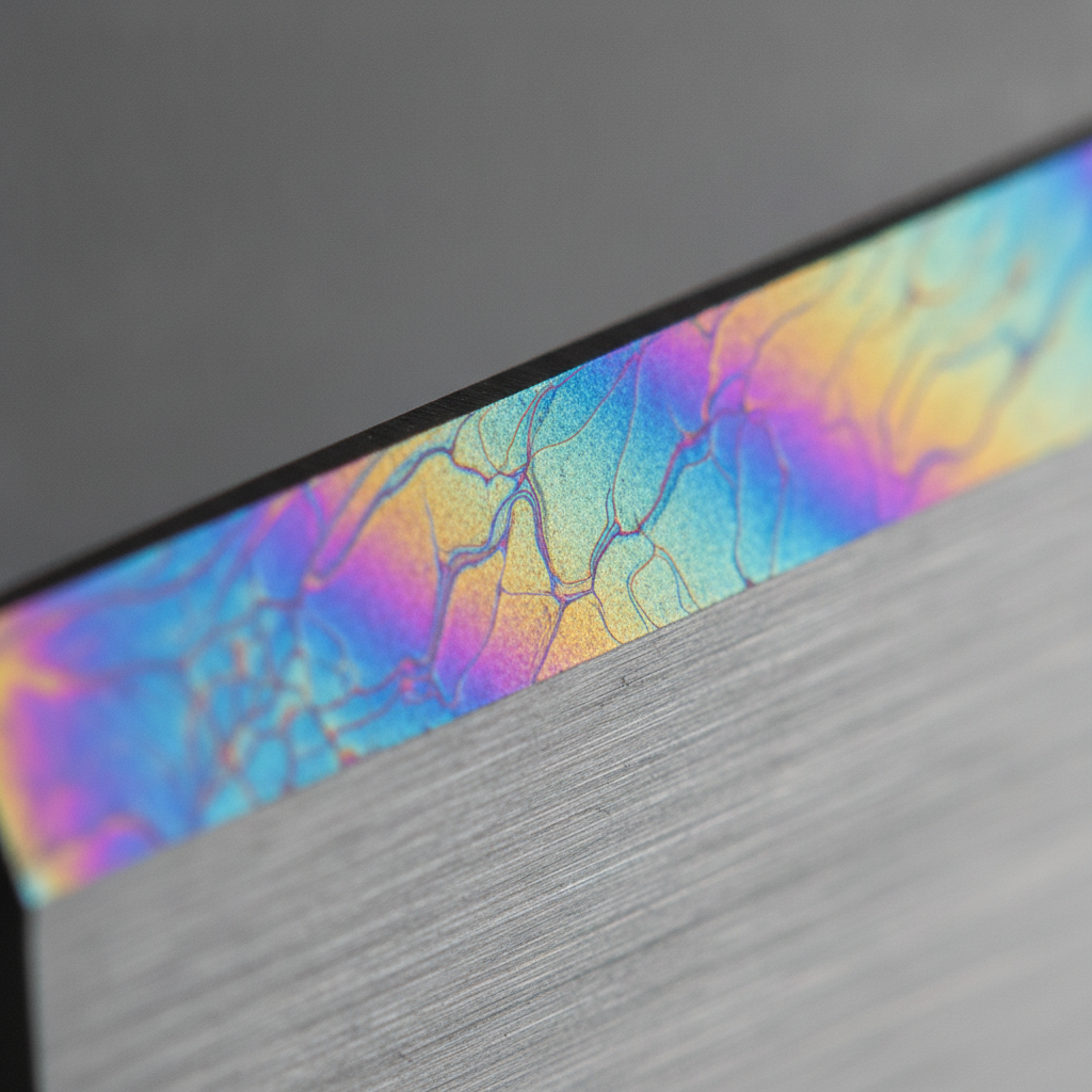
Metal vapor deposition is a vacuum process that converts solid source materials into a vapor and condenses them as a thin, dense film on parts. In industry, it typically refers to PVD coatings like TiN, TiCN, AlTiN, and DLC that improve hardness, reduce friction, and enhance corrosion resistance on tools and components.
In surface engineering, “metal vapor deposition” and “PVD” are used interchangeably. The outcome is a controlled thin film, usually 1–5 μm thick (sometimes up to ~10 μm), with hardness commonly in the 1,800–3,500 HV range for nitride families. DLC variants push friction coefficients toward ~0.1 in dry sliding, which stabilizes cycle-to-cycle consistency.
Sputtek specializes in physical vapor deposition (and complementary Thermospray/Pulsed HVOF) for mission‑critical manufacturing sectors. Our engineering-led approach pairs coating selection with part preparation, fixturing, and post-processing, so the film you specify is the film you see in production.
For a deeper intro to PVD in the Deposition cluster, see our PVD guide for Woodbridge, which contextualizes thin-film behavior on common tooling alloys.
Plain-language definition your team can reuse
- Process: Evaporate or sputter material in vacuum; condense onto parts.
- Film types: Nitrides, carbides, carbon-based (DLC), and multilayers.
- Typical goals: Cut wear, reduce sticking/galling, improve corrosion tolerance.
- Usual thickness: 1–5 μm; tightly controlled for precision tooling.
- Expected effects: 2–5× tool life improvements are common when process details are right.
Why metal vapor deposition matters for manufacturers
Metal vapor deposition raises uptime by curbing abrasive wear, adhesion, and corrosion on production tooling. The result is fewer changeovers, more consistent dimensions, and steadier surface finish. In high-volume operations, even single-digit scrap reductions translate to meaningful capacity and quality gains.
Here’s the thing—most plants don’t fail for lack of effort; they fail for lack of surface control. Wear, friction, and part-to-part sticking rob you of minutes each hour. Metal vapor deposition attacks those loss mechanisms directly, enabling stable performance over longer intervals.
- Longer intervals between changeovers: Hard films resist abrasion and microchipping, supporting 2–4× tool life improvements when paired with correct prep and load density.
- Lower friction and sticking: DLC and tailored nitrides reduce pickup and galling on sheet or resin contact, protecting finish and dimensional stability.
- More predictable Cpk: Stable surface interactions yield tighter distributions, cutting scrap and rework risk.
- Better cleanliness: Engineered surfaces shed residue faster, easing clean-in-place or between-run maintenance.
These benefits map directly to Sputtek’s customers in stamping, plastic injection molding, cutting, and die casting. If your team is exploring DLC options, our DLC coating guide walks through application patterns and selection tips for production tooling.
How metal vapor deposition (PVD) works: step-by-step
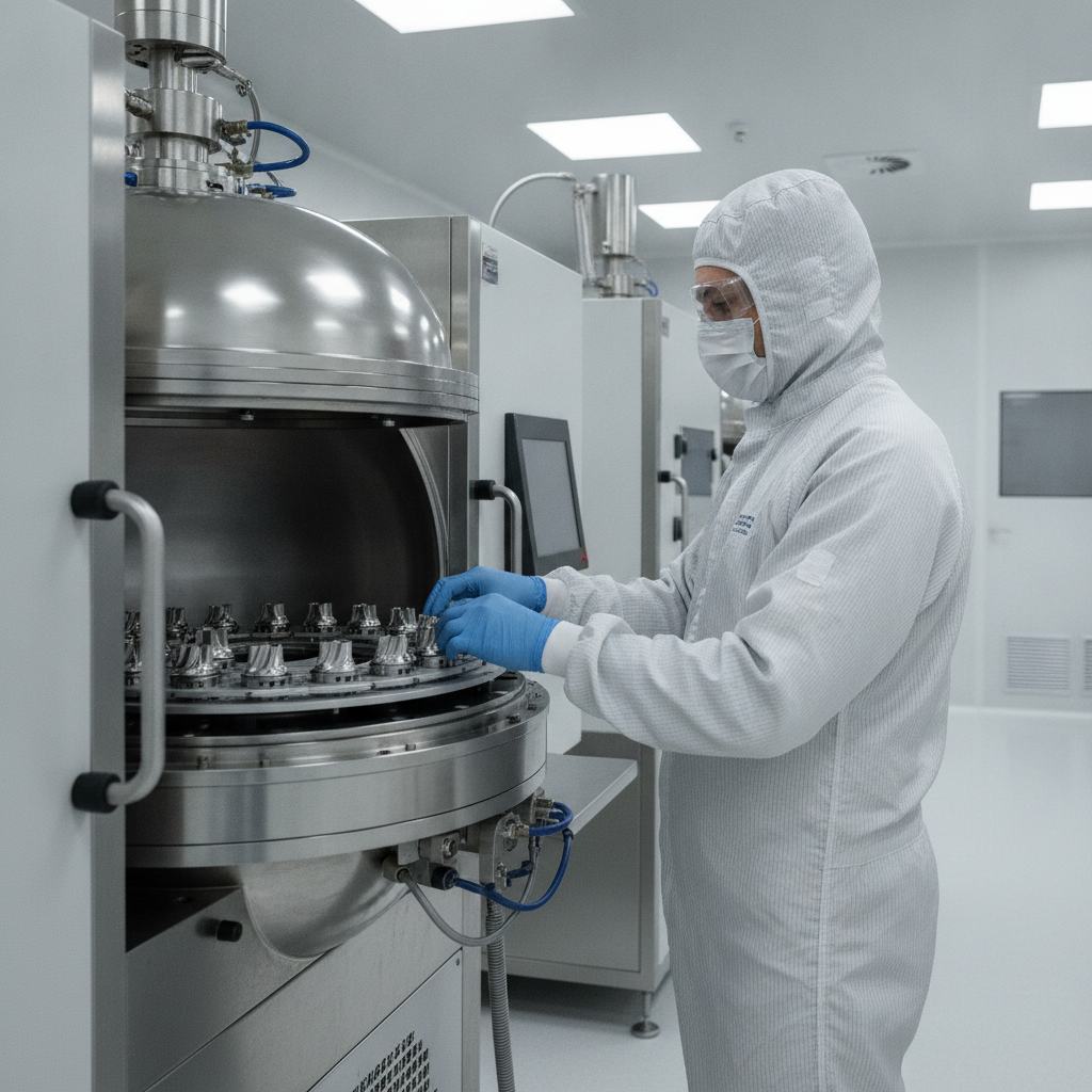
PVD works by moving source material from solid to vapor in vacuum, then condensing it onto parts as a dense film. Sputtering, cathodic arc, or evaporation generates the vapor; bias and temperature tune adhesion, stress, and microstructure. Success depends on clean surfaces, correct fixturing, and controlled energy at the substrate.
The mechanics are straightforward, but control is everything. Adhesion, residual stress, texture, and roughness each respond to how you clean, mask, fixture, bias, and heat parts. Here’s the practical loop our teams follow daily:
- Surface preparation: Degreasing and cleaning, then micro/sandblasting where appropriate, ensures the substrate is chemically clean and mechanically keyed.
- Masking and fixturing: Protect critical interfaces; present uniform angles to the vapor; avoid line-of-sight shadowing that causes thickness gradients.
- Load density and orientation: Batch uniformity governs thickness variation (often targeted within ±10–15%).
- Plasma activation: Pre-clean plasma or bias etch strips remaining contaminants and activates the surface for nucleation.
- Deposition: Sputtering, arc, or evaporation forms the film—parameters control energy-in and growth.
- Post-process: Controlled cool-down; optional lapping/polishing to dial-in Ra and bearing area.
- QC release: Thickness, adhesion, microhardness, and surface roughness checks confirm conformance.
For foundational background on alloys and general metal behavior, some teams consult broad overviews like this general metal education page. While not coating-specific, such primers can help cross-functional stakeholders align on base metallurgy before discussing thin films.
Methods: PVD vs CVD vs HVOF (Thermospray) — when to use each
Choose PVD for hard, thin, line-of-sight films at moderate temperatures. Use CVD for conformal coverage where higher heat is acceptable. Select HVOF/Thermospray for thicker, non-line-of-sight overlays that repair or armor components. Matching method to the operating pain point is the fastest way to reliable results.
Sputtek delivers PVD and Thermospray (including Pulsed HVOF). We help clients decide which path fits their operating window—temperature limits, geometry, and the failure mode you’re fighting (abrasive wear, adhesion, corrosion, or thermal fatigue).
| Method | Typical thickness | Process temperature | Coverage | Best for | Common materials |
|---|---|---|---|---|---|
| PVD (metal vapor deposition) | 1–5 μm (thin) | ~150–500°C (alloy dependent) | Line-of-sight | Wear, friction, clean release | TiN, TiCN, AlTiN, CrN, DLC |
| CVD | 5–15 μm (thin-to-medium) | ~700–1,000°C | Highly conformal | Complex geometry, diffusion bonding | TiC, TiN, Al2O3 |
| HVOF (Thermospray) | 25–500+ μm (thick) | Substrate stays relatively cool | Non-line-of-sight capable | Corrosion armor, dimensional restore | WC-Co, Inconel, stainless, Ni-based |
If you’re comparing thin films to thermal spray for a specific failure mode, our Thermospray perspective complements this article. See our PVD deposition guide for the thin‑film side and our coating alternatives discussion inside the PVD finishing guide.
Real-world selection patterns
- Stamping dies (AHSS, aluminized steels): AlTiN/CrN stacks limit abrasive wear and pickup; DLC helps with adhesive behavior on aluminum sheet.
- Injection molds (glossy cavities, cores, pins): DLC or CrN for clean release and finish retention; thin films preserve detail.
- Cutting tools (end mills, drills): AlTiN/AlCrN families handle heat and abrasion for longer runs in ferrous alloys.
- Die cast/extrusion tooling: Nitrides for thermal fatigue resistance and scale control; smooth post-lap manages soldering risk.
- Components (pins, shafts, valves): DLC to reduce friction and boundary wear in mixed-lubrication regimes.
Best practices that determine coating success
Successful metal vapor deposition hinges on preparation, fixturing, and measurement. Clean substrates, correct masking, uniform load density, and documented QC (thickness, adhesion, roughness) turn “a coating” into a controlled surface that performs repeatably across batches.
In our experience, 80% of coating outcomes are won or lost before the chamber door closes. Here’s the playbook our Woodbridge teams run for production results:
Preparation and masking
- Degrease and clean thoroughly: Any residue can become a defect site; use validated cleaning routes and gloves-only handling.
- Blast judiciously: Micro/sandblast only when compatible with tolerance and finish targets; control media and pressure tightly.
- Mask smartly: Protect fits, seal faces, and critical datum features; design masks that also stabilize orientation.
Fixturing and load design
- Present uniform angles: Avoid deep recesses or occlusions; mitigate with rotation and multi-axis fixtures.
- Target batch uniformity: Keep load density consistent run-to-run to maintain thickness within ±10–15% bands.
- Balance thermal mass: Mixed-mass loads can drift film stress and microstructure; stage or separate when needed.
Process and QC controls
- Plasma activation and bias: Use bias etch to enhance adhesion and manage stress.
- Film build and stress: Monitor for curling tendencies on thin sections; adjust parameters or layer architecture.
- Measure what matters: Thickness (calibrated), adhesion (tape/scribe, scratch), microhardness, roughness (Ra/Rz), and friction benchmarks.
When low friction is a core need, review the application notes in our DLC coating process overview. For stainless components, this stainless with PVD primer shows how to preserve finish while gaining durability.
Soft CTA: Want a quick second opinion on surface prep or fixturing? Share a print and 1–2 photos. Our Woodbridge engineering team will flag the top risks and a practical inspection plan for your first article.
Tools and resources you can leverage
Sputtek combines high-capacity PVD systems with in-house prep and QC. From prototype trials to large-batch runs, the same engineering playbook governs cleaning, masking, fixturing, deposition, and release testing—so results scale predictably from pilot to production.
- High-capacity PVD: Multiple systems including large-load SPUN-class capability for consistent large-batch outcomes.
- Complementary processes: Thermospray (including Pulsed HVOF) for thick overlays where thin films aren’t the right tool.
- End-to-end in-house: Sandblasting, microblasting, degreasing, stripping/polishing, after-coating lapping, and QC lab testing.
- Engineering support: Application-based coating selection with fixturing and inspection guidance.
- Documentation: ISO 9001:2015 quality system with traceable records from incoming to release.
Explore more thin-film specifics in our PVD plating explainer and the practical notes in our PVD finishing guide.
Case studies and examples (tooling and components)
Across stamping, molding, cutting, and die casting, metal vapor deposition routinely delivers 2–4× life improvements with tighter finish control. The biggest wins come from pairing the right film with correct prep, fixturing, and post-lap—so contact mechanics stay stable across long runs.
Stamping (AHSS and aluminum sheet)
- Problem: Edge wear and pickup on draw beads and trim steels.
- Approach: AlTiN/CrN stack to balance heat, oxidation, and lubricity; local DLC for aluminum-contact zones.
- Result: Fewer polish interruptions; improved panel finish uniformity over multi-shift production.
Plastic injection molding (ejector pins, gates, glossy cavities)
- Problem: Sticking parts and micro-scratching that degrades gloss.
- Approach: DLC on pins/cores; CrN in areas needing chemical resistance; light post-lap to target Ra.
- Result: Cleaner release, steadier cycle times, and glossier molded surfaces across campaigns.
Cutting tools (end mills and drills)
- Problem: Edge rounding and heat-softening reduce tool life.
- Approach: AlTiN or AlCrN families with matched edge prep; batch consistency emphasized.
- Result: Longer intervals between offsets; steadier dimensional control.
Die cast and extrusion tooling
- Problem: Soldering, heat checking, and scale impact surface quality.
- Approach: Nitrides with tuned stress and smooth post-lap; optional Thermospray armor on non-critical surfaces.
- Result: Better surface integrity across shots, fewer interventions.
Components (pins, shafts, valves)
- Problem: Boundary wear and high friction in mixed-lubrication regimes.
- Approach: DLC variants tuned for friction and counterface compatibility.
- Result: Lower friction signatures and extended maintenance intervals.
Local considerations for Woodbridge
- Plan pickups around the Weston Rd / Highway 7 corridor to avoid peak congestion when moving tooling between plants and our facility.
- Seasonal humidity swings can nudge surface cleanliness—tighten bagging and handling protocols in summer to preserve prepped surfaces.
- If you’re coordinating multiple vendors, consolidate prep and post-lap locally; proximity near SmartCentres Woodbridge simplifies same-day handoffs.
Frequently Asked Questions
These are the coating questions we hear most from manufacturing engineers and production teams. Each answer is short and practical, designed for quick sharing with stakeholders who need clear, non-jargon explanations.
What thickness should I specify for PVD on tooling?
Most production tools run 2–4 μm for a balance of durability and dimensional control. Very fine features may target 1–2 μm. Thicker builds can increase residual stress and alter edge geometry, so align thickness to tolerance, roughness, and the failure mode you’re solving.
How hot can parts get during PVD?
Substrate temperatures typically range ~150–500°C depending on alloy and film. Tool steels tolerate the higher end; certain stainless or heat-treated parts may require lower schedules. When temperature is constrained, consider lower-energy PVD routes or a thermal-spray solution instead.
How do I evaluate adhesion without lab gear?
Start with validated tape/scribe checks and a visual under good lighting. Track edge wear and delamination signatures during early runs. For quantitative data, use scratch testing and cross-sectional evaluation. Strong adhesion begins with rigorous cleaning, bias etch, and compatible substrates.
When is DLC better than a nitride like AlTiN?
Pick DLC when low friction and clean release are central (e.g., pins, glossy molds, or aluminum contact). Choose AlTiN/AlCrN when heat and abrasion dominate (e.g., hard cutting in steels). Some tools mix films by zone to handle different contact mechanics.
Can PVD help with corrosion on components?
Yes. Dense nitride or DLC layers improve barrier properties and reduce galvanic risk, especially when paired with stainless substrates and good sealing. For severe attack or dimensional restoration, a thicker HVOF/Thermospray overlay may be the better fit.
Conclusion and next steps
Metal vapor deposition delivers durable, predictable surfaces when preparation, fixturing, and QC are disciplined. If you align film chemistry to the actual failure mode—and lock the process details—you can expect longer intervals, steadier finish, and better capacity without disruptive changeovers.
Ready to translate concepts into production results? Our Woodbridge team applies the same engineering playbook from prototype trials to large-batch runs, so the first successful part scales cleanly to the thousandth.
Key takeaways
- Define the failure mode first—then match PVD, CVD, or HVOF accordingly.
- Win the battle in preparation: clean, mask, fixture, and load consistently.
- Measure thickness, adhesion, roughness, and friction signatures every run.
- Use post-lap/polish to hit finish targets without sacrificing durability.
- Document your recipe so success repeats across shifts and batches.
Let’s engineer a coating that fits your line. Book a discovery session with Sputtek’s Woodbridge team, and we’ll outline a validation path for your first article and production ramp.
Related topics in the Deposition cluster
If you’re mapping the broader Deposition landscape, pair this guide with deep dives on DLC behavior, finishing strategies, and stainless applications. Together, they form a working reference you can use to train teams and standardize specifications.
For selection nuance on carbon films, see our DLC coating guide. To connect process parameters to finish outcomes, the PVD finishing guide compiles practical checklists. And for a fundamentals refresher, our PVD plating explainer breaks down terminology your cross-functional team can share.
For general background reading on metals and materials (useful when onboarding cross-functional teammates), some readers reference broad primers like this overview of metal uses or specialized lab notes such as a vitrification study to align on materials behavior. These aren’t coating manuals, but they help establish shared vocabulary.


