
Last updated: October 2026
Manufacturers usually investigate vapor deposition coating when an existing tool, mold, or component is wearing too quickly, sticking during production, losing its finish, or requiring more corrosion protection. The coating is not a substitute for sound design or suitable base material. It is a controlled surface treatment that can change the way a part interacts with its working environment while leaving most of the substrate unchanged.
This guide is written for engineers, toolmakers, maintenance teams, and purchasing groups comparing PVD coating services. It explains the process in practical terms, identifies the information a coating provider needs, and shows where thin-film PVD or DLC differs from a thicker Thermospray solution.
What is vapor deposition coating?
Vapor deposition coating is a broad term for depositing a solid material onto a substrate after the coating material has entered a vapor or highly energetic particulate phase. The result is a functional layer on the surface rather than a change throughout the entire part. Depending on the process, the source material may be vaporized, sputtered, ionized, or carried in a thermal spray stream.
Physical Vapor Deposition, or PVD, is the most common thin-film approach discussed in tooling and precision manufacturing. In a vacuum chamber, a metal or compound source is converted into energetic species that travel toward prepared parts and condense on their surfaces. A related process can deposit diamond-like carbon, commonly called DLC, when low friction and sliding performance are important.
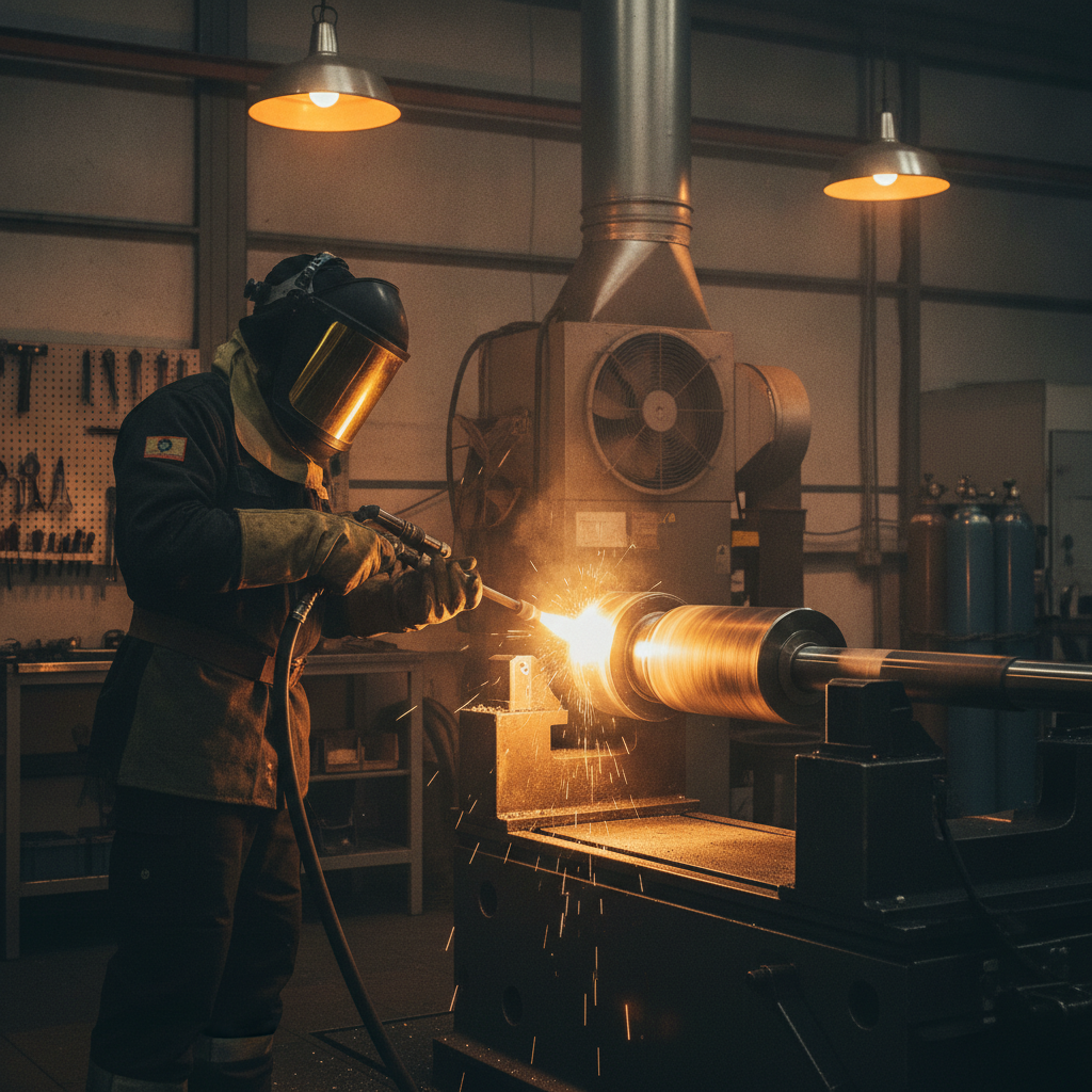
Thermal spray is also a surface-deposition family, but it is not the same as conventional vacuum PVD. Thermospray or Pulsed HVOF accelerates heated particles toward a component to create a substantially thicker layer. That makes it useful for wear barriers, corrosion protection, and dimensional restoration where a one-to-five-micron film would not provide enough material.
For foundational terminology, the PVD deposition guide provides a useful companion reference. The practical distinction is simple: PVD and DLC generally preserve fine geometry with thin films, while Thermospray is selected when the job needs a robust build-up that can be machined or ground back to size.
What performance problems can a coating address?
The correct coating depends on the failure mechanism rather than on the coating name alone. A coating may be considered when the dominant problem is abrasive wear, adhesive wear, galling, friction, release, oxidation, corrosion, or repeated surface damage. The base material, counterface, lubricant, temperature, load, speed, and cleaning environment all affect the outcome.
- Wear: A hard PVD film can protect a tool surface against repeated contact, abrasion, and sliding.
- Friction and release: DLC is often investigated for sliding interfaces and mold surfaces where reducing adhesion or sticking matters.
- Heat and oxidation: Aluminum- or chromium-containing films may be considered for demanding cutting or forming environments, subject to the actual operating conditions.
- Repair and restoration: Thermospray can add enough material to restore a worn shaft, roll, or sealing surface before final finishing.
A coating does not automatically double tool life or guarantee a particular coefficient of friction. Those outcomes must be validated against the part material, process window, preparation quality, and acceptance criteria. Treat published ranges as starting points for engineering discussion, not as a substitute for a coating trial.
How to choose the right coating process
The first decision is usually whether the part needs a thin functional film or a thicker engineered layer. Ask how much material the surface needs, whether the geometry must remain sharp, how much heat the substrate can tolerate, and whether the coating will be finished after application.
| Process | Typical role | Relative layer scale | Important decision factors |
|---|---|---|---|
| PVD | Hard, thin protective film | Often about 1–5 μm | Substrate temperature, film chemistry, adhesion, edge geometry, and fixture orientation |
| DLC | Low-friction carbon-based film | Often about 1–3 μm | Counterface, lubrication, load, temperature, and desired surface finish |
| Thermospray or Pulsed HVOF | Wear or corrosion barrier and dimensional build-up | Often tens to hundreds of microns | Required build, heat input, bond preparation, porosity, and final grinding |
| CVD | High-temperature conformal deposition in selected applications | Application-dependent | High process temperature, substrate compatibility, and geometry |
For a general overview of thin-film vocabulary, see the PVD plating basics guide. PVD is not electroplating: the part is placed in a controlled vacuum environment, and the film is created from a vaporized or sputtered source rather than from an aqueous plating bath.
PVD for tools, molds, and precision parts
PVD is a strong candidate when the part needs a hard, thin layer without a substantial dimensional change. Common film families include TiN, TiCN, CrN, AlTiN, and AlCrN. The best choice depends on the substrate and the combination of wear, heat, oxidation, friction, and visual requirements.
Thin films still matter in a tolerance stack. A coating applied to both sides of a cylindrical feature can increase the effective diameter by approximately twice the radial film thickness, before any polishing or lapping allowance is considered. Drawings should therefore identify coated surfaces, masked surfaces, datums, fits, and any required post-coat finishing.
DLC for friction and release
DLC describes a family of carbon-based coatings rather than one single recipe. DLC may be evaluated for sliding components, forming tools, plastic-processing surfaces, and applications where a low-friction interface or clean release is more important than maximum hot hardness.
The mating material and operating conditions are decisive. A low friction value measured against one steel pair under one test condition should not be treated as a universal production result. Tell the coating provider whether the counterface is steel, aluminum, polymer, or another material, and provide information about lubrication, load, speed, and temperature.
Thermospray and Pulsed HVOF for build-up
Thermospray or Pulsed HVOF is usually the more practical direction when the required layer is far thicker than a PVD film or when a worn surface must be restored. The deposited layer can then be ground, polished, or otherwise finished to the required dimension.
This approach requires a different drawing and inspection plan from PVD. Specify the required finished size, minimum deposited thickness before machining, surface preparation, bond area, final roughness, and inspection points. Long shafts, rolls, sealing areas, and components exposed to corrosion may benefit from this type of engineered build-up when the substrate remains suitable.
How PVD works
PVD begins with part preparation. Oil, fingerprints, oxides, polishing residue, and embedded contamination can interfere with adhesion, so cleaning and surface activation are central to the process. Parts are then mounted so the coating source can reach the functional surfaces as evenly as the geometry allows.
- Review and preparation: The provider checks the drawing, substrate, existing finish, edge condition, masking requirements, and cleaning route. Blasting, polishing, stripping, or other preparation may be required.
- Cleaning and loading: Parts are degreased and cleaned before being placed on fixtures. Handling controls matter because a clean surface can be compromised after inspection.
- Evacuation: The chamber is pumped down to a controlled vacuum. The exact pressure and process sequence depend on the equipment and coating recipe.
- Ion cleaning and activation: Plasma or ion treatment can remove residual contamination and help establish the conditions needed for adhesion.
- Film deposition: A metallic or ceramic source is evaporated or sputtered, and the resulting species condense on the parts. Reactive gases may be used to form compounds such as nitrides.
- Cooling, unloading, and inspection: The parts are cooled and examined for coverage, thickness, appearance, adhesion, and any customer-defined criteria.
Line-of-sight behavior is important. Recesses, deep cavities, threads, and shielded surfaces may receive different coverage from exposed faces. Rotation and fixture design can improve uniformity, but they do not eliminate geometric limitations. A coating review should therefore include a model, drawing, or representative part rather than relying only on a generic film name.
The metal vapor deposition overview gives additional context on source materials, vacuum deposition, and production planning. The useful engineering question is not simply “Can this part be coated?” but “Which surfaces need the film, how evenly must it be applied, and how will the finished part be verified?”
Design and preparation requirements
Many coating failures begin before the part reaches the chamber. A successful production program connects the part drawing, preparation route, coating recipe, finishing method, and inspection plan. The following checklist helps teams identify risks early.
Control edges and corners
Very sharp edges can concentrate stress and may be more vulnerable to chipping or uneven coverage. Where the application permits, specify an edge hone or radius suitable for the tool and coating. Do not add a generic radius to a sealing edge, cutting edge, or shutoff without checking the functional requirement.
Conversely, a coating should not be used to hide a poor edge condition. If a cutting tool needs a defined edge preparation, include that preparation before coating and verify it after finishing.
Define surface roughness before and after coating
Surface roughness influences adhesion, friction, release, and the final appearance. The target before coating may differ from the target after coating, particularly when a mold face or sealing surface will be lapped or polished. Use a clear measurement direction and identify the surfaces that require inspection.
For a practical comparison of finishing choices and post-coat work, consult the PVD finishing guide. Finishing must be selected carefully: aggressive removal can reduce the available film thickness or alter a functional edge.
Plan masking and fixturing
Mark no-coat areas, threads, fits, grounding points, and inspection locations on the drawing or a masking sketch. Include enough information for the provider to understand which surfaces are critical and which can accept incidental coverage.
Fixturing affects both coverage and repeatability. Overcrowding a rack, placing parts too close together, or presenting a complex face away from the source can create variation. A representative production load is more useful than a single idealized sample when the goal is a repeatable process.
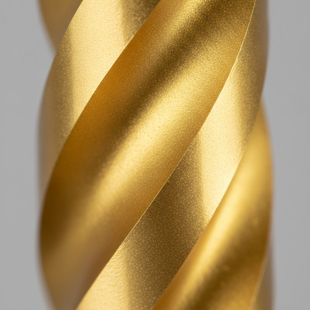
Confirm substrate and heat limits
Provide the substrate grade, prior heat treatment, hardness, tempering condition, and any areas that must not be exposed to the process temperature. PVD process temperatures vary by coating system and recipe, so the provider must evaluate the actual part rather than applying a universal temperature assumption.
Parts that cannot tolerate the selected PVD cycle may need a different film, a different process window, or another surface-treatment route. The same applies to assemblies, brazed components, inserts, and materials with different thermal expansion behavior.
What to include in a coating specification
A good coating request gives the provider enough information to recommend a process and quote the work without guessing. It should describe the part, the failure mode, the working conditions, the required surfaces, and the acceptance criteria.
- Part identity: Drawing number, revision, quantity, material, heat treatment, and whether the parts are new, worn, stripped, or previously coated.
- Application: Tool, mold, shaft, forming component, sliding part, cutting tool, or another function, together with the production problem being addressed.
- Operating conditions: Contact material, load, speed, temperature, lubrication, chemicals, cleaning method, and expected cycle environment.
- Functional surfaces: Coated areas, masked areas, datum references, threads, fits, edges, and surfaces requiring a specific finish.
- Film requirement: Preferred or proposed coating family, target thickness or range, appearance if relevant, and whether an interlayer or graded stack is required.
- Inspection: Thickness method, adhesion expectation, hardness or friction testing where applicable, roughness, visual criteria, and documentation requirements.
Thickness and dimensional control
Thin PVD films are often selected in the approximate one-to-five-micron range, while DLC applications commonly use a thinner film suited to the geometry and friction target. Thermospray work may require a much thicker deposited layer followed by machining or grinding. These are planning ranges, not automatic specifications.
Allow for the coating on every affected surface. A part that must fit into a bore, for example, may need masking, pre-machining, or post-coat finishing depending on the tolerance. State whether the quoted thickness is measured on a witness coupon, a defined part location, or the component itself.
Adhesion, hardness, and roughness
Adhesion testing should reflect the customer’s risk and the coating system. Scratch testing, visual examination, and process records may be appropriate for one job, while a more detailed qualification plan may be justified for a safety-critical or regulated application. Define the acceptance rule before production rather than debating failed parts after delivery.
Hardness values are method- and coating-dependent, especially for very thin films where the substrate can influence the measurement. Similarly, a roughness reading is meaningful only when the instrument, direction, location, and surface condition are controlled. Ask the provider how each reported value is obtained.
Quality documentation can include coating batch identification, cleaning and preparation records, thickness results, adhesion results, roughness readings, photographs, and nonconformance handling. Sputtek describes in-house preparation and quality-control capabilities for PVD and Thermospray work, but the required documentation should still be agreed for each program.
Planning vapor deposition coating in Woodbridge
For a Woodbridge manufacturer, the practical challenge is often coordination rather than terminology. Parts may move from a toolroom to cleaning, coating, lapping, inspection, and back into production within a narrow maintenance window. A complete drawing package and a stable traveler reduce questions at each handoff.
Sputtek’s stated facility address is 110 Sharer Rd, Woodbridge, Ontario, L4L 8P4, Canada. Local teams can use that proximity when planning pickup, delivery, fixture return, or a small qualification batch, but the schedule should be confirmed against the actual part quantity, preparation requirements, coating route, and inspection plan.
Send representative parts when possible. A production-like batch reveals fixture density, masking time, handling issues, and finishing requirements that a single sample may not expose. If the component is too large or valuable for an initial trial, provide a detailed drawing, material and heat-treatment information, photos of the failure, and the surfaces that must remain unchanged.
For teams comparing supplier capabilities, the DLC coating services guide explains the information needed to evaluate a low-friction coating program. For a Woodbridge-focused explanation of thin-film terminology, see the Woodbridge thin-films explainer.
A practical qualification sequence
- Record the failure: Photograph the worn or damaged surface and identify when the problem appears in the production cycle.
- Characterize the job: Confirm substrate, hardness, mating material, load, speed, temperature, lubricant, chemicals, and cleaning conditions.
- Choose the process family: Compare thin PVD or DLC with a thicker Thermospray build based on geometry, thickness, heat, and finishing needs.
- Review the drawing: Add coated and masked surfaces, edge conditions, datums, roughness, dimensional allowances, and inspection points.
- Run a representative trial: Use realistic parts or a representative load, then inspect the coating against pre-agreed criteria.
- Release the production recipe: Record preparation, fixturing, coating, finishing, inspection, and packaging requirements so future batches are comparable.
Common mistakes to avoid
Choosing a coating before defining the failure
TiN, DLC, AlTiN, AlCrN, and Thermospray are not interchangeable labels. A visually attractive film may still fail if the counterface, temperature, load, or substrate is wrong. Begin with the wear or friction mechanism and then select a process that can address it.
Ignoring the post-coat operation
Some surfaces are ready after coating; others require lapping, polishing, grinding, or dimensional inspection. If the finishing route is not included at the start, a film can be damaged, an edge can be altered, or the assembly tolerance can be lost.
Using unsupported performance guarantees
Tool life, friction, corrosion resistance, and cycle improvements are application results, not universal properties. A sound qualification compares coated and uncoated parts under the same production conditions and records the failure criterion that matters to the customer.
Providing too little information for a quote
A coating provider can recommend more accurately when the request includes the drawing, material, quantity, dimensions, required surfaces, operating environment, current failure, and delivery constraints. “Coat this part” rarely provides enough information to select preparation, masking, film, and inspection requirements responsibly.
Frequently asked questions
What is vapor deposition coating used for?
It is used to improve the surface performance of tools, molds, cutting components, sliding parts, and other manufactured items. Depending on the process, the objective may be greater wear resistance, lower friction, improved release, corrosion protection, or restoration of a worn surface. The right process depends on the substrate and operating conditions.
Is DLC the same as PVD?
No. PVD describes a group of vacuum deposition processes, while DLC describes a family of carbon-based films that can be deposited using specialized vacuum processes. DLC is generally considered when low friction, release, or sliding performance is important; other PVD films may be more suitable for hot hardness, oxidation resistance, or abrasive wear.
How thick is a PVD coating?
Many PVD applications use a thin film in the approximate one-to-five-micron range, although the appropriate value depends on the coating, substrate, geometry, and application. DLC is often applied in a similarly thin range, while Thermospray is selected when the part needs a much thicker layer. The specified thickness must be considered together with masking, tolerances, and post-coat finishing.
Will vapor deposition coating change part dimensions?
Yes. Any deposited film changes the dimensions of the coated surfaces, even when the change is small. Account for the film on all affected faces, and identify whether the part will be lapped, polished, ground, or measured as-coated before it enters production.
What should I send when requesting PVD coating services?
Send the current drawing and revision, material and heat-treatment details, quantity, coated and masked surfaces, target roughness, dimensional tolerances, operating conditions, and a description of the failure or performance goal. Photos of wear and representative parts are also useful. This information allows the provider to compare PVD, DLC, and thicker Thermospray options instead of recommending a film in isolation.
Move from coating selection to a controlled production process
Vapor deposition coating is most effective when it is treated as an engineered production step rather than a generic finish. Define the failure, choose between thin PVD or DLC and a thicker Thermospray build, then control substrate condition, masking, fixturing, finishing, dimensions, and inspection.
For a Woodbridge project, a drawing review and representative trial can turn an uncertain coating request into a repeatable specification. Sputtek can review the application information and help determine whether PVD coating services, DLC, or Thermospray best fits the part and its production environment.
Request a technical coating review
Share the part drawing, material, operating conditions, failure photographs, and required delivery window with Sputtek’s surface-engineering team to discuss a coating and finishing route for your application.