
pvd equipment: selection criteria, process types, and maintenance essentials
Choosing pvd equipment is a strategic decision that touches process capability, part quality, throughput, and long‑term operating costs. This guide breaks down how the technology works, the main process families, which specifications matter, how to plan for utilities and floor space, and the maintenance routines that keep uptime high. You will also find a practical buying checklist you can adapt to your application.
What is PVD equipment?
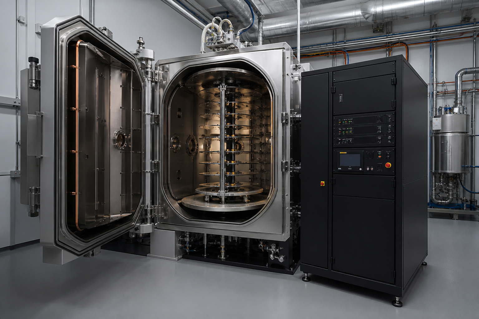
Physical Vapor Deposition (PVD) equipment is a vacuum‑based system that creates thin, adherent coatings by vaporizing a solid material and depositing it onto parts. The result is a functional surface layer engineered for properties such as wear resistance, low friction, thermal stability, barrier performance, or decorative appearance. Typical coated parts include cutting tools, stamping dies, molds, medical components, aerospace hardware, and production machine elements.
While configurations vary, most systems feature:
- Vacuum chamber with pumping stack (roughing and high‑vacuum stages)
- Power supplies matched to the chosen deposition sources (e.g., magnetron sputtering, arc evaporation)
- Substrate handling and fixturing to rotate or bias parts for uniform coverage
- Gas delivery for process and reactive atmospheres (e.g., argon, nitrogen)
- Thermal management (heaters, cooling circuits) to achieve and control substrate temperature
- Controls, data logging, and safety interlocks
PVD process types and where they fit
Different PVD source technologies produce different ionization levels, energy at the substrate, and growth kinetics. Understanding the practical differences helps you match a system to your parts and coatings.
- Magnetron sputtering (DC/AC/RF): A gas plasma dislodges atoms from a target which then condense on substrates. Known for smooth films, tight thickness control, and excellent uniformity—well suited to functional and decorative coatings, diffusion barriers, and multilayers.
- High‑power impulse magnetron sputtering (HiPIMS): Pulsed high‑power sputtering increases ionization, enabling dense films and strong adhesion. Useful where high toughness or intricate coverage is needed.
- Cathodic arc evaporation: Material is vaporized from cathodic spots, yielding highly ionized flux and high deposition rates. Often used for hard nitride and carbide coatings on tools and dies. Managing macroparticles (droplets) is a key consideration.
- E‑beam evaporation and thermal evaporation: Evaporate materials by heating, producing line‑of‑sight deposition. Common for optical, decorative, and some barrier layers; typically lower energy at the substrate than sputter or arc.
Many systems are hybrid, combining sputter and arc sources to broaden capability—for example, depositing an adhesion layer by sputtering followed by a hard topcoat via arc. When evaluating options, map your target materials (e.g., TiN, CrN, DLC‑related stacks, oxides) and geometry (line‑of‑sight vs. complex cavities) to the source technology and fixturing approach.
Critical specifications to compare
Beyond chamber size, several specifications directly influence coating quality, cycle time, and consistency. Comparing them side‑by‑side helps avoid mismatches.
- Usable chamber volume and load mass: Look at practical loading volume and allowable mass per cycle, not just overall chamber dimensions. This affects throughput and part spacing for uniformity.
- Pumpdown performance: Base pressure capability and time to pressure influence cleanliness and cycle time. Consider vacuum architecture (pumps, throttling, conductance) and outgassing management.
- Power density at targets: Determines achievable deposition rates and film structure. For magnetron systems, magnet pack design and target utilization impact both rate and cost per run.
- Substrate bias control: Stable bias improves film density and adhesion. Review bias range, waveform options, and how bias interacts with rotation/planetary motion.
- Thermal envelope: Substrate temperature limits can constrain materials and substrates. Check heater power, uniformity, and cooling to protect heat‑sensitive components.
- Gas handling and flow control: Mass flow controller range, response, and repeatability matter in reactive sputtering (e.g., nitrides, oxides). Closed‑loop partial pressure control can stabilize stoichiometry.
- Thickness uniformity: Confirm stated uniformity zones (e.g., within ±X% over defined fixture diameter). Uniformity depends on source geometry, part spacing, and motion profiles.
- Contamination control: Baffles, shutters, and shields reduce cross‑contamination during material changes and help maintain clean deposition zones.
- Automation and recipes: Recipe management, event logging, and interlocks simplify training and ensure repeatability across shifts.
- Changeover ergonomics: Target swaps, shield replacement, and fixture handling time directly affect uptime and cost per part.
Fixturing and load configuration
Even the best process sources cannot overcome poor part presentation to the vapor flux. Effective fixturing is central to coating performance and consistency.
- Rotation strategy: Single rotation vs. planetary motion balances simplicity and uniformity. Complex geometries typically benefit from multi‑axis rotation.
- Line‑of‑sight management: Shadowing and self‑occlusion are mitigated with tilt angles, staggered tiers, and part spacing. Perform mock‑loads to visualize sightlines.
- Electrical contact: Reliable electrical paths support stable bias and heating. Contacts should be located to avoid cosmetic areas when possible.
- Thermal coupling: For temperature‑sensitive parts, fixtures that distribute heat and provide controlled cooling reduce thermal gradients.
- Material compatibility: Fixture materials must withstand process temperature and avoid contaminating films. Shield coverage should be easy to service.
Plan for dedicated fixtures for high‑volume SKUs and configurable fixtures for prototype or mixed loads. Document loading patterns; minor deviations can shift thickness and film stress.
Utilities, footprint, and environment
pvd equipment integrates into a broader facility ecosystem. Early planning prevents costly retrofits and smooths qualification.
- Electrical: Confirm voltage, phase, peak and average current, and power quality needs for pumps and plasma supplies. Consider dedicated circuits and surge protection.
- Cooling water: Chilled and process water flows, temperature stability, and cleanliness are essential for pumps, targets, and power supplies. Heat rejection capacity affects building HVAC.
- Process gases: Argon and reactive gases require appropriate purity, delivery pressure, and distribution safety. Provide isolation and purge capability for maintenance.
- Exhaust and ventilation: Manage heat load and any byproducts consistent with safety guidance. Ensure service access around the machine for shields and target changeouts.
- Floor loading and access: Check slab capacity and doorway/aisle clearances for installation. Leave space for cranes or lifts if loads are heavy.
- Cleanliness and prep: Pre‑cleaning areas (degrease, bead/microblast) reduce contamination and stabilize cycle times. Segregating dirty prep from clean loading bays helps process control.
Quality and process control
Coating performance depends on how well you manage inputs and verify outputs. Build measurement into the process from receiving to final release.
- Pre‑clean checks: Surface roughness and base material condition influence adhesion. Track incoming condition and cleaning recipes.
- In‑process monitoring: Log pressures, flows, power, bias, and temperature. Alarms and trend charts help detect drift before it affects product.
- Witness coupons: Place standard coupons in repeatable positions to gauge thickness, hardness proxies, and adhesion tests according to your internal methods.
- Post‑process finishing: Light polishing or lapping may be specified to meet friction or roughness targets without removing critical film thickness.
- Documentation: Recipe control, revision history, and lot traceability enable root‑cause analysis and regulatory audits where applicable.
Maintenance and reliability
Reliability starts with a serviceable design and continues with disciplined care. A predictable maintenance plan protects throughput and film quality.
- Shielding strategy: Use replaceable shields on walls, around sources, and near load ports. Scheduled replacements prevent flaking that can seed defects.
- Pump health: Monitor pumpdown curves, vibration, and oil (for applicable pumps). Replace seals and service foreline traps according to hours and conditions.
- Target lifecycle: Track erosion profiles and change before arcing or nonuniform utilization affects rate or uniformity. Maintain spare targets to avoid extended downtime.
- Calibration: Regularly verify mass flow controllers, pressure gauges, pyrometry/thermocouples, and power readbacks. Calibration drift can silently degrade coatings.
- Electrical connections: Inspect high‑current and bias connections for heat discoloration or looseness. Poor contacts cause instability and arc events.
- Cleaning regimen: Non‑abrasive cleaning of viewports, sensors, and fixtures preserves measurement integrity and repeatability.
Create a maintenance calendar that distinguishes daily checks (visuals, leaks, basic logs), weekly tasks (shield inspections, residue mapping), and campaign‑based overhauls (deep cleans, pump service). Record findings; trends often predict failures better than single data points.
Total cost of ownership and buying checklist
Initial machine cost is only one part of the equation. A clear view of total cost of ownership (TCO) helps you select the right platform and scale capacity with fewer surprises.
- Throughput vs. takt time: Model parts per load, cycle time (including pumpdown and changeover), and yield to estimate effective output.
- Consumables and wear items: Targets, shields, seals, and filters can dominate recurring cost. Estimate usage by coating family and duty cycle.
- Utilities: Electricity, cooling, and gases scale with recipe and runtime; include them in cost per part models.
- Floor space and infrastructure: Factor lease, HVAC, and building upgrades such as chillers or power distribution.
- Uptime and serviceability: Mean time to repair, spare availability, and ease of preventive maintenance directly affect output and delivery performance.
Use this practical checklist to structure vendor conversations and internal reviews:
- Define target coatings, substrates, and part geometries; collect drawings and sample parts for fixturing discussions.
- Specify performance outcomes (e.g., thickness range, uniformity band, hardness proxies, surface finish targets) and how you will measure them.
- Choose a source technology (sputter, arc, hybrid, evaporation) aligned to your films and geometry; validate with sample runs if possible.
- Confirm usable load volume, mass per cycle, and rotation/planetary options; review example loading patterns for your parts.
- Review pumpdown curves, base pressure, and contamination controls (shields, shutters, material changeover procedures).
- Assess thermal capability (heating/cooling range and uniformity) relative to substrate tolerances.
- Evaluate controls: recipe management, data logging, alarms, and remote access policies as applicable.
- Detail utilities (power, cooling, gases), exhaust/ventilation, and floor loading; plan installation logistics and service access.
- Examine maintenance tasks, spare parts lists, and recommended intervals; map to your staffing and shifts.
- Build a TCO model: consumables, utilities, labor, maintenance, and expected uptime; compare scenarios (single large system vs. multiple smaller units).
- Document validation steps: first‑article criteria, coupon locations, and acceptance reports for internal sign‑off.
FAQs
What coatings are typically produced with PVD?
Common families include nitrides (e.g., TiN, CrN), carbides, oxides, and multilayer stacks tailored for properties such as wear resistance, thermal stability, corrosion barriers, and optical or decorative effects. The exact stack depends on part material, geometry, and operating environment.
How do I estimate coating uniformity before purchase?
Review the vendor’s stated uniformity zone and request thickness maps from representative parts or witness coupons placed in positions similar to your intended load. Validate with a trial run when possible, using your fixturing concept and spacing to capture real‑world results.
Does higher deposition rate always improve cost per part?
Not necessarily. Rate must be balanced with film properties, uniformity, pumpdown time, heating/cooling ramps, and changeover time. A slightly slower process with faster changeovers or better yield can outperform a high‑rate recipe in overall takt time and cost per part.