PVD plating is a vacuum deposition process that bonds ultra-thin, hard ceramic films to metal or polymer parts to cut wear, reduce friction, and resist corrosion. At 110 Sharer Rd in Woodbridge, Sputtek applies PVD and DLC coatings for manufacturers seeking longer tool life, stable cycles, and cleaner, more consistent output.
By Ron, Sputtek • Last updated: 2026-06-21
Quick Summary
PVD plating (physical vapor deposition) deposits ultra-thin, hard, and adherent coatings—like TiN, CrN, AlTiN, and DLC—inside a vacuum chamber. It delivers higher hardness, lower friction, and better temperature stability than electroplating. For production teams, that translates to longer tool life, tighter quality, and fewer changeovers.
This complete guide focuses on real-world use in industrial manufacturing. You’ll learn what PVD is, how it works, where it beats alternatives, and how to spec coatings that scale from prototype to large batches under ISO controls.
- What PVD plating is and why it matters to uptime
- How the process runs—from prep to QC—step by step
- Which chemistries fit stamping, molding, machining, and components
- Best practices to lock in repeatable adhesion and thickness
- How Sputtek in Woodbridge supports regulated industries with ISO 9001:2015 and Nuclear N299.3 approval
- Definition
- Why it matters
- How it works
- Methods and coatings
- Comparison to alternatives
- Best practices
- Tools and resources
- Case snapshots
- FAQ
What is PVD plating?
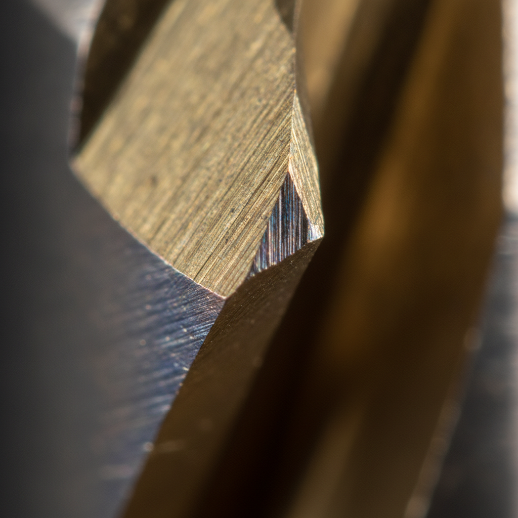
PVD plating is physical vapor deposition: a vacuum process that converts solid coating materials into vapor and condenses them as dense, hard films on parts. Typical layers are 1–5 microns thick with high adhesion and controlled chemistry, improving wear, friction, and corrosion behavior versus bare substrates.
Many buyers say “pvd plating,” while engineers say “PVD coating.” In practice, they refer to the same family of vacuum-deposited thin films. These films include nitrides (TiN, CrN, AlTiN) and carbon-based layers (DLC) that form engineered surfaces with reliable hardness and low friction.
At Sputtek’s modern 15,000 sq ft facility in the Greater Toronto Area, multiple PVD systems support prototypes and high-volume runs alike. Our engineering-led team prepares surfaces in-house—sandblasting, microblasting, cleaning, stripping, polishing, and lapping—so adhesion and finish are predictable before a single part enters the chamber.
Why PVD plating matters for manufacturers
PVD plating reduces friction, hardens surfaces, and stabilizes performance at temperature. For production teams in Woodbridge and the Regional Municipality of York, that means fewer stoppages, more predictable cycles, and longer intervals between maintenance—especially on high-load or abrasive operations.
Surface conditions control scrap rate, uptime, and yield. A thin, hard PVD layer resists abrasion and built-up edge, while smoother, lower-friction surfaces release parts cleanly from molds and dies. Compared with untreated steel, PVD-coated tools typically maintain edge geometry longer and run cleaner between services.
- Wear resistance: Nitrides like TiN, TiCN, CrN, and AlTiN offer hardness typically in the ~1800–3500 HV range, slowing abrasive wear.
- Low friction: DLC’s dry contact friction can approach ~0.1, which helps sliding components and anti-stick scenarios.
- Thermal stability: AlTiN and AlCrN maintain hot hardness under high-speed machining and thermal cycling.
- Cleanliness: Vacuum deposition avoids wet-chemistry residues common to some electroplating lines.
- Dimensional control: At 1–5 µm, PVD layers protect without materially shifting tight tolerances.
Teams in regulated sectors—automotive, aerospace, oil & gas, nuclear, medical, pharmaceutical, and food & packaging—choose Sputtek for coatings that must be consistent, traceable, and repeatable under ISO 9001:2015 and Nuclear N299.3 controls.
How PVD plating works (step-by-step)
PVD runs in a sealed vacuum. Parts are cleaned, fixtured, heated, then exposed to vapor from sputtering or arc evaporation. Reactive gases form nitrides, carbides, or carbon films that condense as thin, dense layers. Rotation ensures even thickness; in-situ controls lock down adhesion and chemistry.
- Pre-clean and activation: Degreasing, sandblasting/microblasting, and plasma cleaning remove contaminants and open the surface for bonding.
- Load and vacuum: Parts are racked to minimize shadowing; the chamber is pumped down to high vacuum to enable clean film growth.
- Heat and bias: Substrate temperature and bias voltage tune internal stress, density, and adhesion of the film.
- Vapor generation: Targets are sputtered or arc-evaporated; metal ions/atoms enter the gas phase in a controlled plume.
- Reactive chemistry: Gases like nitrogen (nitrides) or hydrocarbon species (DLC) combine with metal vapor to form the coating.
- Growth and rotation: Fixtures rotate; geometry, masking, and dwell balance thickness across edges, bores, and faces.
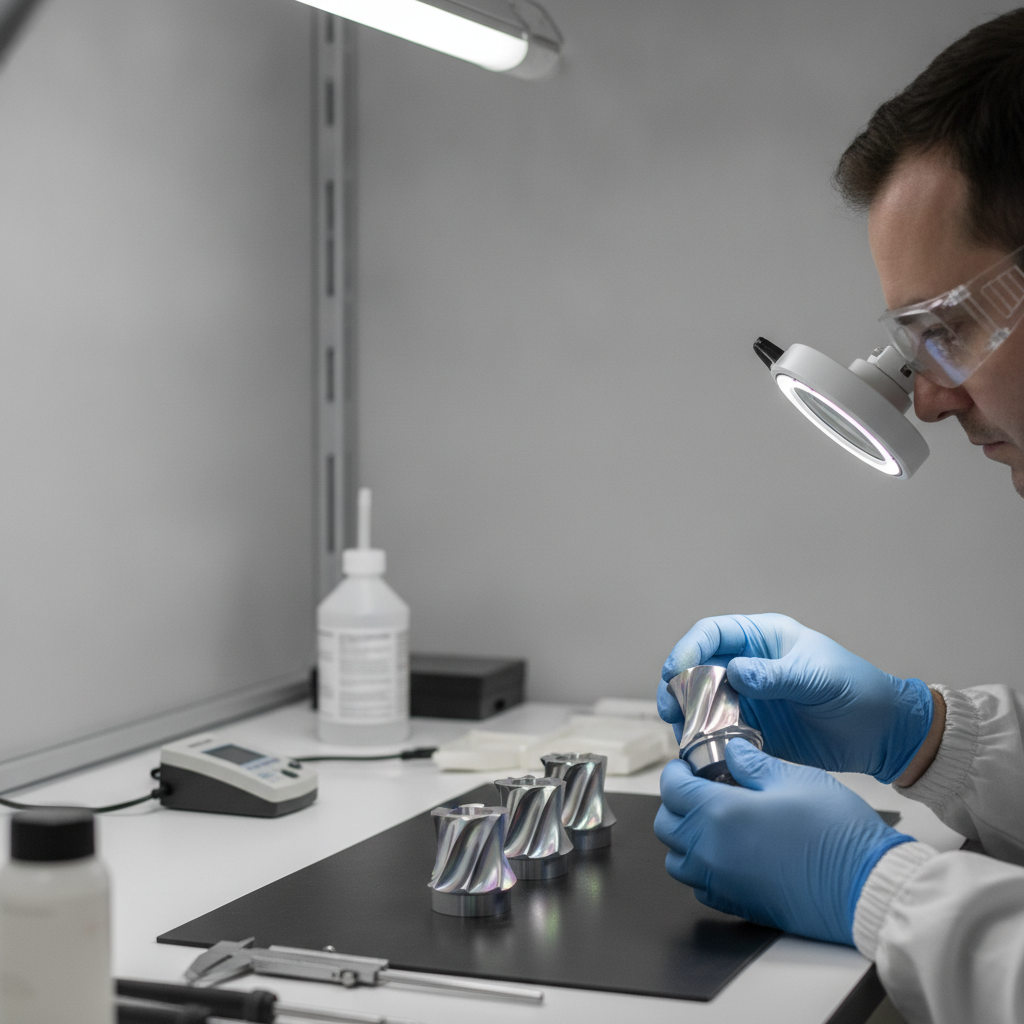
- Cool-down and QC: Thickness, adhesion, hardness, and even color are verified before release to production.
Each of these variables—cleanliness, heat, bias, gas composition, part orientation—can make or break adhesion. That’s why we keep pre-/post-processing and QC in-house. It shortens feedback loops and stabilizes results from lot to lot.
PVD methods, common coatings, and when to use each
Two primary PVD methods dominate: magnetron sputtering (smooth, precise) and arc evaporation (high ionization, very dense). Popular films—TiN, TiCN, CrN, AlTiN, and DLC—span use-cases from stamping and molding to high-speed machining and low-friction components.
Methods
- Magnetron sputtering: Offers excellent thickness control and smooth morphology. Ideal for low Ra requirements, optical smoothness, and parts sensitive to roughness. See our sputtering best practices for deeper guidance.
- Arc evaporation: Generates highly ionized species for very dense, adherent films with strong edge retention. Useful when severe abrasion or impact demands extra toughness.
Workhorse coatings
- TiN (gold): General-purpose wear layer; often ~1800–2100 HV; common on steels and carbides for dies, punches, and decorative-plus-functional hardware.
- TiCN (blue-gray): Lower friction than TiN; effective on forming tools and punches where galling must be avoided.
- CrN (silver): Combines corrosion and galling resistance; a favorite for plastic molds, food tooling, and components that see moisture or cleaning cycles.
- AlTiN / AlCrN: Higher hot-hardness; excels in dry, high-speed cutting where thermal loads drive edge breakdown.
- DLC (diamond-like carbon): Very low friction with good wear resistance; suited for sliding components, precision valves, and tablet tooling where anti-stick behavior matters. For details, explore our DLC coating guide.
Application fit (quick picks)
- Stamping dies and punches: TiCN or CrN to combat galling and abrasion.
- Plastic injection molds: CrN on cores/cavities for release and mild corrosion control; pre-polish to low Ra, then post-lap as needed.
- Cutting tools: AlTiN/AlCrN for hot-hardness in dry, high SFM machining; TiN for general-purpose finishing.
- Pharma and food tooling: DLC for anti-stick and low friction; CrN where cleaning and corrosion exposure are routine.
- Components and fasteners: TiN or DLC for wear and sliding efficiency with minimal dimensional impact.
PVD vs electroplating, CVD, and HVOF (quick comparison)
Compared with electroplating, PVD delivers harder, thinner, and cleaner films with better temperature stability. Versus CVD, PVD runs at lower temperatures. HVOF builds thick, dense overlays but lacks PVD’s micro-thin precision. Choice depends on wear mode, heat, geometry, and cleanliness needs.
| Attribute | PVD | Electroplating | CVD | HVOF/Thermal Spray |
|---|---|---|---|---|
| Typical thickness | 1–5 µm | 5–25 µm+ | 2–10 µm | 50–500+ µm |
| Hardness (indicative) | ~1800–3500 HV | ~150–600 HV | ~2000–3500 HV | ~800–1300 HV |
| Process temperature | ~150–500°F class | Ambient | ~900–1830°F | Ambient to warm |
| Adhesion | Metallurgical + mechanical | Mechanical/chemical | Metallurgical | Mechanical |
| Friction | Low (esp. DLC) | Moderate | Moderate–low | Moderate |
| Corrosion behavior | Thin barrier; pair with CrN | Material dependent | Material dependent | Good barrier (thick) |
| Geometry coverage | Line-of-sight; manageable | Conformal | Line-of-sight | Line-of-sight |
| Cleanliness | Very high | Varies; wet chemistry | High | Powder residue managed |
| Ideal use | Precision wear control | Decorative/corrosion | High-temp wear | Thick rebuilds |
Thermal spray processes like HVOF and Thermospray excel when you need thick, dense overlays or to reclaim dimensions. PVD shines when you need a micro-thin, very hard, low-friction surface that preserves tolerances. At Sputtek, we run both PVD and Thermospray/Pulsed HVOF, so we can recommend the right path—sometimes a hybrid approach works best.
Best practices for specifying PVD
Define the wear mode, substrate, finish, and operating temperature. Choose coating chemistry to counter the dominant failure mechanism. Control pre-clean, masking, and fixturing. Validate with thickness and adhesion checks, then lock down a coating spec so production runs are repeatable across batches.
Start with the problem statement
- Failure mode: Is the limit abrasive wear, galling, adhesion build-up, corrosion, or heat softening?
- Operating window: What speeds/feeds, temperatures, lubricants, and cleaning cycles are typical?
- Tolerance sensitivity: How much thickness can the part accept (1–5 µm typical)?
Map chemistry to the failure
- Abrasive wear: TiN/TiCN or AlTiN/AlCrN depending on heat.
- Galling/adhesion: CrN or DLC to lower friction and resist pick-up.
- Corrosion exposure: CrN as a thin barrier; consider stainless substrates where possible.
- Heat-driven edge loss: AlTiN/AlCrN for hot-hardness in dry cutting.
Control the prep and fixtures
- Surface prep: Sandblasting/microblasting and cleaning remove embedded abrasives and oils that sabotage adhesion.
- Finish: Pre-polish mold surfaces; post-lap after coating to achieve ultra-low Ra if required.
- Fixturing: Document orientation and masking. Consistency here eliminates thickness drift and color variation.
Validate and lock the spec
- Thickness window: Define a target (e.g., 2–4 µm) with measurement method and location.
- Adhesion test: Agree on a protocol and acceptance criteria suitable for the substrate and film.
- Traceability: Lot records, parameters, and QC results support regulated-industry requirements.
For a deeper tactical playbook, see our PVD finishing guide and this PVD process walkthrough. Together they outline how prep, fixturing, and vacuum parameters interact in production.
Tools and resources you can leverage
Leverage in-house blasting, microblasting, cleaning, stripping, and lapping to stabilize adhesion and surface finish. Use high-capacity PVD systems for scale, and a QC lab to verify thickness, hardness, and adhesion before release. Pair PVD with Thermospray/HVOF when thick overlays are needed.
- End-to-end prep: Sandblasting, microblasting, degreasing, and plasma cleaning—executed in-house for consistency.
- High-capacity systems: SPUN 2,000 (up to ~1,200 kg/cycle) and SPUN 4,000 (up to ~3,000 kg/cycle) support large, mixed production.
- Post-processing: Polishing and lapping to restore or improve Ra after coating.
- QC laboratory: Thickness checks, adhesion testing, hardness verification, color tolerance, and documentation.
- Complementary processes: Thermospray & Pulsed HVOF for thick, dense overlays; PVD for micro-thin precision—combined where appropriate.
Explore our PVD types overview for more on method selection, and this DLC coating guide when friction is the primary constraint.
Request a coating assessment: If you manage stamping, molding, machining, or component lines and want to stabilize uptime, we’ll review wear modes, geometry, and finish to map the fastest path to a repeatable spec.
Real-world examples and quick case snapshots
Across stamping, molding, machining, and component manufacturing, PVD plating typically extends tool life, reduces scrap, and stabilizes cycle times. These snapshots illustrate how chemistry and prep choices map directly to outcomes in production.
Stamping
Forming dies and punches often fail from galling and abrasion. TiCN or CrN reduce adhesion and scuffing while preserving edge definition. With consistent fixturing and a 2–4 µm window, shops report cleaner part release and more predictable service intervals.
- Challenge: Adhesion build-up on dies causing surface scratches.
- Approach: Pre-polish, microblast, TiCN layer, and post-lap on critical radii.
- Result: Smoother draw surfaces and fewer mid-run stoppages for cleaning.
Plastic processing
Mold cores and cavities benefit from CrN’s anti-galling and mild corrosion resistance, especially under frequent cleaning. Thin films preserve vent features and dimensional fidelity.
- Challenge: Part sticking and scuffing on textured cavities.
- Approach: CrN with tight Ra control; document orientation to balance texture coverage.
- Result: Cleaner release and shorter mold maintenance cycles.
Machining and cutting
For high-speed, dry cutting, AlTiN/AlCrN maintain hot-hardness and edge integrity. TiN remains a reliable generalist for finishing passes and mixed operations.
- Challenge: Edge breakdown at elevated SFM.
- Approach: AlTiN with bias tuning for dense growth; verify thickness at cutting lips.
- Result: More stable tool wear patterns and consistent surface finish.
Components
DLC’s low friction helps valves, pins, and sliding mechanisms move with less torque and heat. Where cleaning cycles or moisture are present, CrN offers thin, protective barriers.
- Challenge: Sliding wear and stick-slip behavior in dry environments.
- Approach: DLC on contact areas with documented masking of bores and threads.
- Result: Smoother motion and steadier performance over longer intervals.
Local considerations for Woodbridge
- Plan drop-offs and pickups near SmartCentres Woodbridge to avoid peak traffic windows.
- Seasonal humidity swings can influence incoming surface condition; request sealed packaging in summer.
- For tight timelines, coordinate shipments along Weston Rd / Highway 7 corridors for predictable lead logistics.
PVD plating in context with materials and finishes
PVD interfaces with substrate metallurgy, cleaning chemistries, and downstream finishes. Dialing in pre-polish, masking, and lapping ensures your thin film enhances—not hides—design intent. For polymers, surface energy and release strategy matter just as much as thickness.
When polymer tooling or components are in play, base material selection affects cleaning, adhesion, and wear behavior. For a general overview of polymer families that show up in industrial tooling, see this primer on thermoplastic vs. thermosetting polymers. It’s not a PVD guide, but it helps frame substrate constraints that influence surface engineering decisions around coatings, textures, and release.
Cleanliness and material purity influence whether a coating bonds or peels. In lab environments, purity control starts upstream; in production, it’s enforced by robust pre-clean and handling. For background on purity control concepts from a materials perspective, this overview on ensuring high purity in manufacturing workflows provides useful context.
Finally, PVD should not be confused with decorative ceramic sealants used on consumer finishes. For contrast, see this discussion of ceramic coatings over protective films—a different category than industrial PVD, but a reminder that “coating” spans very different technologies.
Frequently Asked Questions
These concise answers address common engineering and operations questions about PVD plating—covering thickness, temperature, geometry, and when to choose DLC or alternate chemistries.
Is PVD plating the same as PVD coating?
Yes. Buyers often say “pvd plating,” while engineers say “PVD coating.” Both refer to vacuum-deposited thin films such as TiN, CrN, AlTiN, and DLC applied for wear, friction, or corrosion control.
How thick is a typical PVD layer?
Most production films land between 1 and 5 microns. That’s thin enough to preserve tight tolerances yet hard enough to resist abrasion. Thickness windows are set by application, geometry, and surface finish targets.
When should I choose DLC over TiN or CrN?
Choose DLC when low friction and anti-stick behavior are the priority—sliding components, tablet tooling, precision valves. Pick TiN/TiCN for general wear on dies and punches, and CrN when galling or mild corrosion are dominant risks.
Can PVD handle complex geometries?
PVD is line-of-sight, but smart fixturing and rotation deliver uniformity on edges, bores, and recesses. Masking and orientation notes in the coating spec are essential for repeatability between batches.
Conclusion and next steps
PVD plating creates thin, hard, low-friction surfaces that stabilize uptime and quality without shifting tolerances. The best results come from matching chemistry to failure mode, controlling prep and fixturing, and validating thickness and adhesion with a locked spec.
Key takeaways
- PVD films are typically 1–5 µm, preserving tight dimensions while adding wear resistance.
- Choose TiN/TiCN for dies, CrN for galling/corrosion, AlTiN for hot machining, and DLC for sliding parts.
- Spec the process: define thickness window, adhesion protocol, and orientation/masking notes.
- Leverage in-house prep, post-lap, and QC to stabilize adhesion and finish across lots.
Action steps
- Document your current failure mode, operating window, and finish targets.
- Share drawings and priority surfaces; we’ll recommend coating chemistry and thickness windows.
- Run a pilot on a representative batch, then lock the spec for volume runs.
Ready to align your coating spec with production reality? Connect with our engineering team at 110 Sharer Rd in Woodbridge to schedule a technical review.


