The physical vapor deposition process is a vacuum thin-film method that turns solid coating material into vapor and condenses it onto parts to create hard, dense layers. Typical coatings are 1–5 micrometers thick with strong adhesion and engineered friction, which boosts tool life and consistency. At 110 Sharer Rd in Woodbridge, Sputtek runs end-to-end PVD for industrial production.
By Ron • Last updated: 2026-06-20
Overview: Physical Vapor Deposition at a Glance
Physical vapor deposition (PVD) is a vacuum coating process where atoms are ejected from a solid source (target) and deposited as a thin film on components. It delivers dense, hard, 1–5 μm coatings with tailored friction and corrosion behavior. Manufacturers use PVD to extend tool life, stabilize quality, and reduce unplanned downtime.
This complete guide explains the physical vapor deposition process end to end—from fundamentals to real production. You’ll see how Sputtek engineers coatings for stamping, plastic molding, cutting tools, and aluminum die cast/extrusion, and when Thermospray/Pulsed HVOF is the better path. Use it to set specs, audit vendors, and plan scale-up.
At a Glance
- What PVD is and how it works in vacuum
- Where sputtering, cathodic arc, HIPIMS, and DLC fit
- Surface prep, fixturing, and QA controls that matter
- Industry examples across tooling and components
- How PVD compares with Thermospray/Pulsed HVOF
- Best practices to lock in adhesion and repeatability
Table of Contents
- What is the physical vapor deposition process?
- Why PVD matters for manufacturers
- How the PVD process works (step-by-step)
- PVD methods and when to use them
- Process controls, QA, and standards
- Materials, substrates, and surface prep
- Applications by industry and use case
- PVD vs Thermospray/Pulsed HVOF
- Best practices to maximize tool life
- Tools and resources: systems and fixtures
- Case snapshots from the floor
- FAQ
- Key takeaways
- Conclusion
What is the physical vapor deposition process?
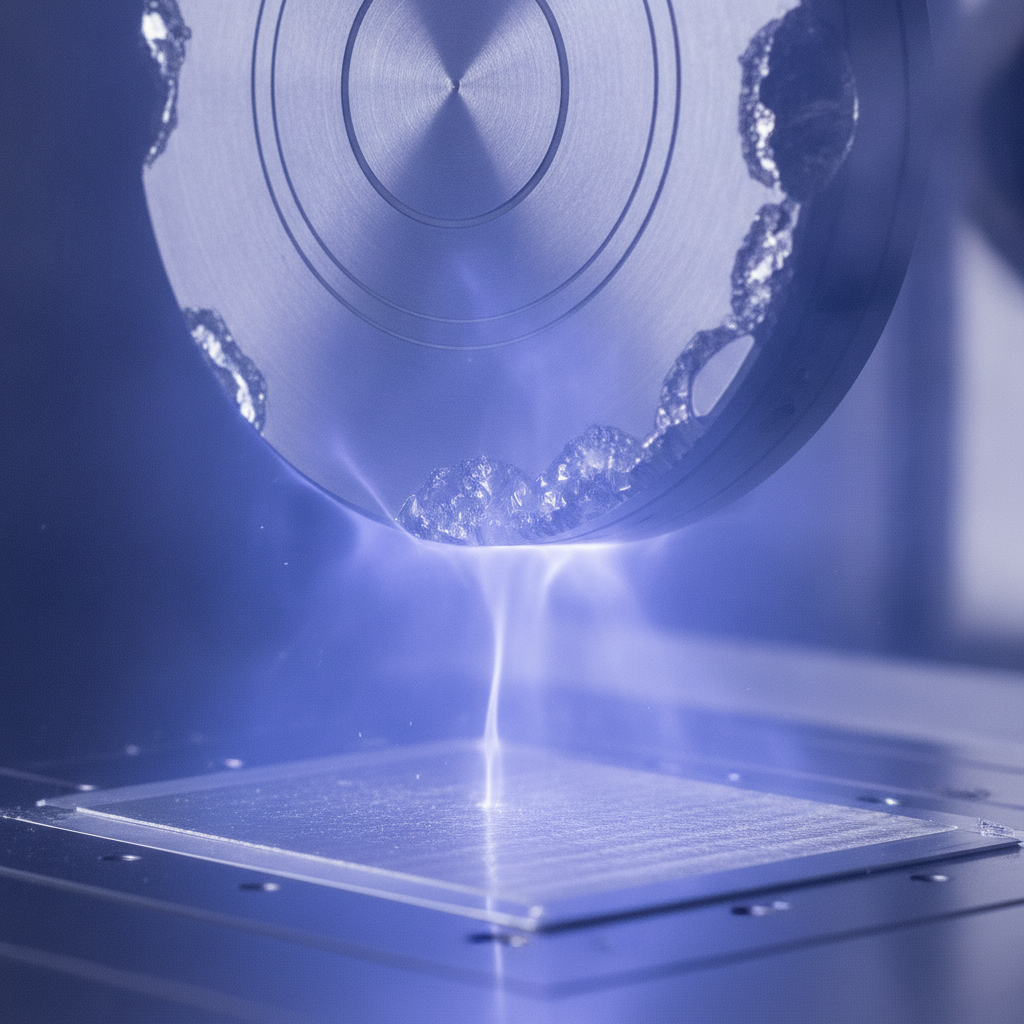
The physical vapor deposition process converts a solid coating source into vapor inside a vacuum chamber and condenses it onto parts as a thin, engineered film. Typical PVD coatings measure 1–5 μm, deliver high hardness, low porosity, and controlled friction, and adhere strongly when pretreatment and fixturing are optimized.
In plain terms, PVD moves atoms from a source (target/cathode) to the surface of your component. Energy input (thermal, plasma, arc, or pulsed power) ejects material, which travels through low-pressure gas and nucleates on the part. The result is a dense, conformal coating that can be tailored for hardness, lubricity, or barrier performance.
Core characteristics
- Film thickness: commonly 1–5 μm; microgeometry is preserved while edges gain protection.
- Adhesion: promoted by clean substrates, bombardment, and interlayers (e.g., Cr, Ti).
- Friction and wear: DLC can reach ~0.1–0.2 coefficient of friction in dry sliding.
- Thermal budget: many alloys tolerate PVD at 150–500 °C with minimal distortion.
Common chemistries
- TiN/TiCN/TiAlN: multi-purpose, oxidation resistance for cutting and stamping.
- CrN/AlCrN: great against adhesive wear and for plastic tooling release.
- DLC (a‑C:H / ta‑C): very low friction and low transfer; ideal for tribology-critical parts.
Where a painted or plated layer can chip or corrode at defects, dense PVD’s columnar-to-nanocomposite structures and low pinhole density deliver stable performance. For regulated sectors, documenting film thickness, microhardness, and adhesion scratch loads builds traceability.
Why PVD matters for manufacturers (Woodbridge & York Region)
PVD boosts mean time between maintenance by protecting edges and sealing surfaces against wear, galling, and corrosion. In Woodbridge and across the Regional Municipality of York, manufacturers use PVD to stabilize yield, shorten changeovers, and maintain capability indices when volumes spike or materials vary.
Why does this matter on the plant floor? Because wear doesn’t just destroy tools—it creates process instability. A 2–3 μm coating that reduces adhesive transfer can keep your parting lines crisp, reduce scrap, and prevent line stoppages. On multi-cavity molds or high-speed stamping lines, the compounded savings are significant over each run.
- Longer tool life: Hard films resist abrasive wear; interlayers block diffusion.
- Lower friction: DLC and AlCrN variants cut stick–slip, easing ejection and release.
- Cleaner surfaces: Less buildup means fewer manual interventions and safer cycles.
- Dimensional stability: Thin films preserve tolerances while protecting edges.
- Traceability: Measured thickness, adhesion, and roughness support quality records.
In our experience supporting automotive, medical, and packaging programs, the biggest unlock is process repeatability. Once tooling is prepared, masked, and fixtured consistently, coating performance becomes predictable—and that predictability drives schedule confidence.
How the PVD process works (step-by-step)
PVD follows a controlled sequence: clean and activate parts, evacuate to vacuum, generate vapor from a target (sputter/arc/HIPIMS), condense atoms onto rotating fixtures, and verify thickness/adhesion. Tight control of pressure, power, bias, and temperature ensures dense, uniform films across all features.
Every successful run starts with disciplined preparation and repeatable controls. Below is the production flow Sputtek uses to build adhesion and uniformity for complex tooling and components.
- Pre-clean & prep: Degrease, ultrasonic clean, and dry. When needed, sandblast/microblast to tune roughness (Ra) and anchor profile.
- Masking & fixturing: Protect critical fits. Mount on rotating trees for line-of-sight coverage and uniform thickness.
- Vacuum & heat: Pump down to low pressure; ramp temperature to remove residual moisture and outgassing.
- Plasma activation: Argon glow discharge sputter-cleaning; optionally add bias to enhance energy at the surface.
- Nucleation/interlayer: Deposit adhesion-promoting layer (e.g., Cr, Ti).
- Main deposition: Sputtering, cathodic arc, DLC, or HIPIMS to build 1–5 μm with rotational uniformity.
- Cool-down & vent: Controlled cooling; avoid moisture shock.
- QC & finishing: Measure thickness (calo/sphereoscope), microhardness, adhesion (scratch), and, if needed, lap/polish.
| Step | Purpose | Key controls | Typical values |
|---|---|---|---|
| Vacuum | Reduce gas collisions | Base pressure | ~10⁻⁶ Torr pre-process |
| Activation | Clean and energize surface | Bias, argon flow | Plasma voltage in 100s of volts |
| Deposition | Build dense film | Target power, pressure | 1–5 μm thickness |
| QC | Verify spec | Thickness, adhesion | Scratch critical load set by spec |
To go deeper on the sputter path, see our PVD sputtering best practices. For a framework on finishing and post-process, our PVD finishing guide outlines polishing and lapping steps that lock in surface performance.
PVD methods and when to use them
Choose sputtering for smooth, droplet-free films and great step coverage; cathodic arc for ultra-dense, high-rate layers; HIPIMS for dense nano-structured films with exceptional adhesion; and DLC for extremely low friction. Match method to geometry, temperature limits, and target tribology.
The method is your lever for film structure and properties. Each approach ejects atoms differently, which drives energy at the surface, density, and defect types. Here’s a practical selector.
Sputtering (DC/RF magnetron)
- Best for: Smooth finishes, low droplet content, and complex geometries.
- Notes: Lower energy than arc; adjust bias/HIPIMS assist to build adhesion.
- Use cases: Plastic molds, fine-feature components, decorative-functional films.
Explore options in our PVD types guide to align targets, gas chemistry, and substrate bias for your part mix.
Cathodic arc
- Best for: Very dense coatings with high ionization; great for wear edges.
- Notes: Microdroplets can require post-polish; energy improves adhesion.
- Use cases: Stamping dies, forming tools, cutting edges.
HIPIMS (High-Power Impulse Magnetron Sputtering)
- Best for: Exceptional adhesion and densification with sputtered smoothness.
- Notes: Pulsed power increases ionization; supports graded layers.
- Use cases: Demanding edge retention, barrier layers under DLC.
DLC (Diamond-Like Carbon)
- Best for: Minimal friction, anti-galling, improved release in dry or marginal lube.
- Notes: a‑C:H variants have hydrogen; ta‑C are hydrogen-free and harder.
- Use cases: Pump components, medical devices, high-cycle tooling.
When the target is ultra-low friction and chemical inertness, DLC is often the answer. See our DLC coating overview and deeper DLC coating guide to pick a stack and substrate pretreatment.
Process controls, QA, and standards
Repeatable PVD depends on documented prep, calibrated power supplies, controlled bias, and verified thickness/adhesion. Certified systems—ISO 9001:2015 and Nuclear N299.3—ensure traceability, from lot prep through final inspection, supporting regulated automotive, medical, and nuclear programs.
Our Woodbridge facility runs multiple PVD systems plus a Thermospray cell and QC laboratory. The value is traceability: batch travelers, calibration records, and inspection data tied to each part number and revision. That’s how you audit runs and prove conformity.
- Surface prep control: Degrease, ultrasonic clean, microblast, and verify roughness (Ra/Rz) before masking.
- Chamber control: Log base pressure, temperature ramps, and process gas flows.
- Power & bias: Stabilize target power; tune bias for adhesion without overheating.
- Thickness: Calotest/sphereoscope spot checks per fixture level; cross-verify with coupons.
- Adhesion: Scratch testing to specified critical loads; use interlayers where needed.
- Post-finish: Lapping/polishing to hit Ra targets or remove arc droplets.
When you need a refresher on finishing choices and benefits, our guide to PVD finishing explains how gentle lapping recovers mirror finishes after arc processes and how polishing affects release on plastic tooling.
Materials, substrates, and surface prep
Adhesion starts long before deposition. Proper alloys, heat treatments, and surface preparation—cleaning, microblasting, and activation—determine whether a 1–5 μm film survives millions of cycles. Fixturing and masking finish the job by aiming uniform thickness at critical edges.
The substrate is part of the coating system. Over-tempered steels can soften; high-silicon aluminums may need specific preps. Our in-house sandblasting, microblasting, stripping, and after-coating lapping compress vendor steps and keep quality under one roof.
- Stamping/tool steels: D2, H13, M2 accept TiAlN/AlCrN well; polish bearing areas to target Ra.
- Plastic molds: P20, H13, S7 benefit from CrN/DLC for release and anti-galling.
- Aluminum tooling: Use barrier underlayers; avoid peening that raises Ra excessively.
- Masking: Protect fits, vents, and datum surfaces to preserve tolerance.
- Fixture strategy: Rotate parts for line-of-sight coverage; shadow test with coupons.
Right after coating, targeted lapping can restore mirror finishes or tune roughness windows for ejection reliability. For complex parts, we often build custom masks and fixtures so the coating goes exactly where it should—and nowhere it shouldn’t.
Applications by industry and use case
PVD protects edges, reduces adhesion, and stabilizes cycles in stamping, plastic injection molding, machining, and aluminum die cast/extrusion. Typical wins include lower scrap, faster ejection, improved wear tracking, and fewer unplanned interventions across automotive, medical, and packaging lines.
Here are concrete examples where the physical vapor deposition process changes outcomes on the floor.
- Progressive stamping dies: AlCrN on punches to curb adhesive wear and edge chipping.
- Draw/trim tools: TiCN/TiAlN stacks for abrasion with improved galling resistance.
- Blanking tooling: Arc-deposited TiN with post-lap for crisp shear planes.
- Plastic injection molds: CrN on cores/cavities for release and reduced buildup.
- Hot runners/gates: DLC on pins for low friction and cleaner flow.
- Cutting tools (HSS/carbide): TiAlN for heat and wear at elevated speeds.
- Thread formers: DLC to cut torque and prevent pickup in dry forming.
- Aluminum extrusion dies: AlCrN to slow washout and extend profile consistency.
- Die cast ejector pins: DLC to reduce soldering and sticking during ejection.
- Pump/valve components: DLC for scuffing protection under marginal lubrication.
- Food & packaging: Hard films for knives, seal bars, and wear tracks with easier clean-down.
To compare these routes at a glance, our overview of PVD coatings maps film chemistries to operating conditions so you can match a stack to each tool family.
PVD vs Thermospray/Pulsed HVOF: choosing the right path
Use PVD for thin, hard, low-porosity films (1–5 μm) with tailored friction on precision surfaces. Choose Thermospray/Pulsed HVOF when you need thicker overlays (50–500+ μm), edge rebuilds, or corrosion/erosion barriers on larger components or worn areas.
PVD and Thermospray solve different problems. PVD modifies surface tribology without changing part geometry. Thermospray builds thickness and barrier mass rapidly. The right choice depends on whether you want a precision skin or a structural overlay.
| Criterion | PVD | Thermospray / Pulsed HVOF |
|---|---|---|
| Typical thickness | 1–5 μm | 50–500+ μm |
| Main benefit | Hardness, low friction | Corrosion/erosion barrier, dimensional restore |
| Geometry impact | Minimal | Measurable build-up |
| Best for | Tool edges, molds, precision parts | Rolls, shafts, housings, large surfaces |
When you suspect you need both—say, a rebuilt surface plus low friction—our engineering team sequences processes so overlays bond cleanly and PVD stacks adhere reliably on top.
Best practices to maximize tool life
Build repeatability with disciplined prep, smart masking/fixturing, and method/chemistry tuned to your wear mode. Validate with thickness and adhesion checks, then use after-coating lapping or polish to hit surface targets. Document everything so the next batch performs the same—or better.
- Start with data: Identify wear modes (abrasive, adhesive, fatigue) and heat zones.
- Prep like it matters: Cleanliness and microblast parameters make or break adhesion.
- Protect tolerances: Mask critical fits and datum features religiously.
- Fixture for flow: Rotate and angle parts to minimize shadowing; place coupons.
- Pick the right stack: Use interlayers and graded layers where adhesion is tough.
- Measure, then polish: Verify thickness before lapping to final Ra.
- Close the loop: Track cycles-to-maintenance and failure modes by tool ID.
For a side-by-side of options, our PVD types overview and sputtering guide outline practical trade-offs for real plant conditions.
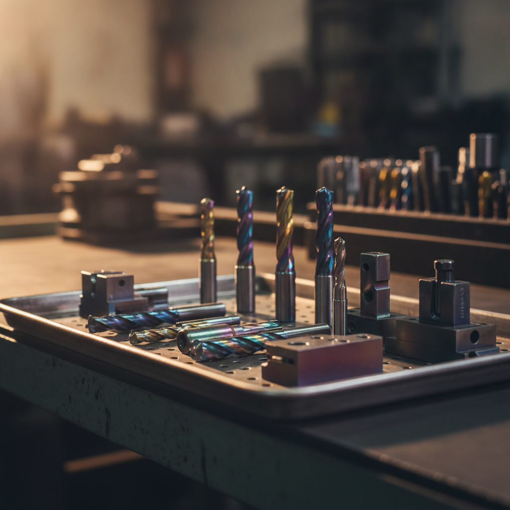
Tools and resources: systems and fixtures
High-capacity PVD systems and purpose-built fixtures keep quality consistent from prototype to large batches. Sputtek’s SPUN 2,000 and SPUN 4,000 platforms handle heavy loads while maintaining vacuum integrity, uniform rotation, and stable power for repeatable film growth.
Throughput and uniformity depend on the chamber and the hardware around your parts. Our engineering team designs custom fixtures and masks to optimize line-of-sight coverage while protecting datums and sealing surfaces.
- SPUN 2,000: Production-class PVD system for mixed tooling and components.
- SPUN 4,000: High-capacity system built for large-batch reliability.
- Custom systems: Tailored to unique part geometries and film stacks.
- Fixture design: Rotating trees and masks to focus thickness where it matters.
Curious which platform fits your mix? Our PVD types overview links to selection guidance, and our DLC resources—starting at diamond-like coating—map friction targets to film families.
Case snapshots from the floor
Short, verified runs prove capability before scale-up. By standardizing prep, stack, and inspection on pilot tools, you predict coating behavior at volume—reducing risk when programs launch or materials change.
We keep client details confidential, but these snapshots reflect typical results seen after implementing a tuned PVD route at our Woodbridge facility.
- Automotive stamping: AlCrN on trim punches reduced adhesive pickup; changeover intervals extended from frequent interventions to planned maintenance windows with stable edge quality.
- Plastic injection: DLC on pins and CrN on cores improved ejection; operators reported smoother cycles and fewer manual assists on a multi-cavity mold.
- Die cast ejection: DLC on ejector pins decreased soldering; dimensional stability maintained across extended runs at elevated die temperatures.
- Precision cutting: TiAlN on carbide form tools supported higher surface speeds while holding roughness and dimension over multiple batches.
Local considerations for Woodbridge
- Plan pickups and deliveries around peak traffic near Weston Rd / Highway 7; schedule early windows to tighten turnaround.
- Seasonal humidity swings can affect incoming cleanliness; request sealed packaging during summer and winter.
- For multi-stop errands, our facility is close to SmartCentres Woodbridge; coordinate logistics with your team to reduce idle time.
Frequently Asked Questions
Engineers ask about adhesion, temperature limits, geometry, and when to prefer Thermospray over PVD. Here are concise answers you can use to plan trials, write specs, and align upstream/downstream processes without delaying production.
What materials can be coated with PVD?
Tool steels, stainless steels, carbides, and many nonferrous alloys accept PVD when heat tolerance and pretreatment are appropriate. Proper cleaning, masking, and interlayers (e.g., Cr, Ti) enable strong adhesion on complex geometries and tight tolerances.
How thick are PVD coatings?
Most industrial PVD films are 1–5 micrometers. That’s thin enough to preserve dimensions while thick enough to resist abrasive and adhesive wear. Thickness targets depend on wear mode, geometry, and whether post-polish or lapping is planned.
When is Thermospray or Pulsed HVOF better than PVD?
Choose Thermospray/Pulsed HVOF when you need a thick overlay, geometry restoration, or robust corrosion/erosion barriers, particularly on large components. Use PVD when you need a thin, hard, low-friction skin that doesn’t alter part dimensions.
Do PVD coatings change tolerances?
PVD films add microns, not millimeters. With masking and fixturing, you can protect datum fits and functional bores while placing coating where it matters—edges and wear tracks. Post-lapping can fine-tune surface finish without losing adhesion.
Key takeaways
PVD is a precise, vacuum-based way to add hard, engineered skins to tools and components without changing their dimensions. The biggest wins come from repeatable prep, disciplined fixturing, and QC that verifies thickness and adhesion before parts hit the line.
- Physical vapor deposition process = dense, 1–5 μm films tuned for wear and friction.
- Method choice (sputter, arc, HIPIMS, DLC) determines structure and tribology.
- Prep, masking, and fixturing are as important as deposition itself.
- QA data (thickness, adhesion) under ISO/N299.3 anchors repeatability.
- PVD complements Thermospray/Pulsed HVOF for thicker barriers and repairs.
Conclusion
Treat PVD as an engineered process, not a black box. When you pair the right chemistry with disciplined prep and QA, you extend tool life, reduce scrap, and protect schedules. The result is steadier cycles, cleaner parts, and fewer surprises for production and quality teams.
Want to validate a stack on your tooling mix? Start with a small, instrumented run. We’ll help you specify prep, chemistries, and QC so you can scale to large batches with confidence.
Considering a pilot? Reach out to our engineering team at 110 Sharer Rd in Woodbridge to plan samples, fixtures, and inspection criteria for your first article run.
Industry perspectives on coatings and operational excellence can help frame your program direction. See discussions on coating integration perspectives and manufacturing leadership spotlights (innovation and sustainability; operational excellence) for complementary context.


