Diamond-like coating (DLC) is a family of hard, low-friction amorphous carbon films applied by PVD/PECVD to reduce wear and extend component life. From our facility at 110 Sharer Rd in Woodbridge, Sputtek uses DLC and advanced PVD processes to help manufacturers cut downtime, stabilize quality, and keep tools running longer in production.
By Ron — Sputtek Surface Engineering
Last updated: 2026-06-19
Summary
Diamond-like coating pairs extreme hardness with ultra-low friction to fight wear, galling, and adhesive buildup. In production, DLC can stabilize cycle time, protect edges, and reduce changeovers. This guide explains what DLC is, how it’s deposited by PVD, where it works best, and the practices that maximize coating performance.
This complete guide is designed for engineering and manufacturing teams evaluating diamond like coating for real parts, dies, and tools. Use it to align stakeholders, choose the right DLC variant, and build a repeatable process from prototype to volume.
- What DLC is and how it works in plain language
- Where DLC shines: stamping, molds, cutting tools, die cast, precision parts
- Process fundamentals: surface prep, fixturing, masking, QA
- Variants: a-C:H, ta-C, doped DLC, WC/C — when to use each
- Benchmarks engineers rely on: hardness (HV), thickness, friction, temperature
- How Sputtek scales DLC with high-capacity PVD systems
What is diamond-like coating (DLC)?
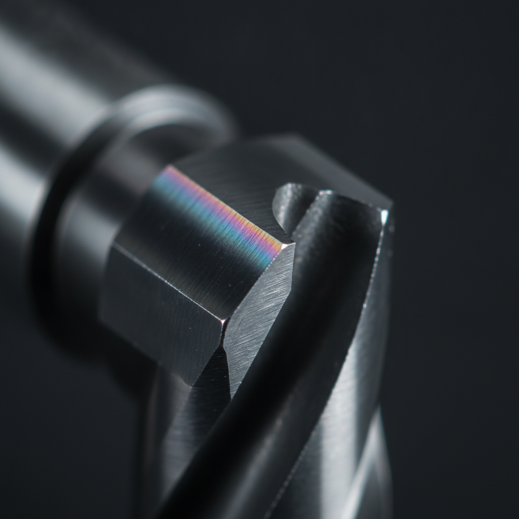
Diamond-like coating is an amorphous carbon thin film that combines diamond-like hardness with graphite-like lubricity. Deposited by PVD/PECVD, DLC typically measures 1–4 µm thick, 1,500–3,000 HV in hardness, and 0.05–0.15 dry coefficient of friction—ideal for reducing wear and sticking on tools and components.
DLC refers to a class of carbon coatings with mixed sp2/sp3 bonding. The high sp3 content delivers hardness; the sp2 content helps lubricity. Variants (hydrogenated, hydrogen-free, doped) tune stress, adhesion, and temperature limits. In practice, DLC is a precision-engineered barrier that resists abrasion, micro-welding, and corrosive attack.
- Hardness range: commonly 1,500–3,000 HV; ta-C variants can exceed this.
- Typical thickness: 1–4 µm for fine-edged tools; up to ~10 µm for heavy-wear parts when geometry allows.
- Friction: 0.05–0.15 dry against steel; often lower with boundary lubrication.
- Temperature envelope: a-C:H often stable to ~300–350 °F; hydrogen-free ta-C performs higher; always confirm by application.
At Sputtek, DLC sits within our broader Deposition toolkit alongside PVD nitrides and carbonitrides. For a deeper primer on deposition families, see our internal overview of PVD coating types and our PVD finishing guide.
Why DLC matters to manufacturers
DLC matters because it breaks the cycle of edge wear, galling, and unplanned changeovers. Plants see steadier cycle times, fewer scrap spikes, and cleaner tools. The net effect: more good parts per shift, longer maintenance intervals, and faster payback on tooling.
When dies or cutters lose edge integrity, everything slows: press tonnage creeps up, burrs grow, polishing expands, and scrap rises. DLC interrupts that pattern by offering very low shear at the interface, paired with a stable hard skin that resists micro-chipping.
- Cycle stability: lower adhesion means fewer stick–slip events; stroke-to-stroke variation tightens.
- Edge retention: a 1–4 µm hard skin protects micro-geometry that defines performance.
- Clean release: reduced pickup on punches, cores, and ejector pins keeps surfaces running cleaner between planned PMs.
- Cross-industry fit: automotive stamping, medical device molding, food & packaging, aerospace fastener forming, and more.
We’ve seen DLC help teams move from frequent hand-polishing to scheduled, data-driven PM windows. For example, a stamping line that previously required touch-up every few shifts stabilized to planned maintenance over multiple runs once diamond like coating was dialed into the process window.
How DLC coating is deposited (PVD/PECVD basics)
DLC is deposited in vacuum using energetic carbon species that condense as an amorphous film. Common routes include PVD sputtering, filtered cathodic arc, and PECVD. Success depends on surface preparation, ion cleaning, tailored interlayers, and precise temperature control.
In our coating cells, parts are cleaned, dried, fixtured, and plasma-activated. Carbon is then introduced and driven to the surface by energetic ions. Adhesion is engineered with metallic or ceramic interlayers (e.g., Cr, Ti, or Si-containing layers) that bridge the substrate and DLC.
- Sputtering (PVD): graphite targets release carbon by ion bombardment; excellent uniformity and stress control.
- Filtered arc (PVD): very high ionization and density; magnetic filtering reduces macroparticles for smooth films.
- PECVD: hydrocarbon gas cracked in plasma; widely used for conformal coatings at moderate temperatures.
- Interlayers: chromium, titanium, or silicon-based layers improve bonding and mitigate residual stress.
- Stress management: pulse parameters, bias, and temperature are tuned to avoid spallation on sharp edges.
For a practical view of our deposition options within the Deposition cluster, explore our pages on types of PVD and detailed PVD sputtering best practices.
Types of DLC and how to choose
Choose DLC by matching variant to load, temperature, and counterface. a‑C:H favors lubricity at moderate heat, ta‑C maximizes hardness and heat tolerance, doped DLC tunes friction or adhesion, and WC/C excels for sliding under boundary lubrication.
Not all diamond-like carbon is the same. The chemistry and hydrogen content shift performance windows and adhesion strategies. Here’s a pragmatic way to navigate options.
a‑C:H (hydrogenated DLC)
- Where it fits: general-purpose sliding, molds and cores, light-to-moderate load stamping, pumps, pins.
- Strengths: very low friction; good release on polymers and sticky alloys.
- Consider: temperature limits compared with ta‑C; verify lube compatibility.
ta‑C (hydrogen-free, tetrahedral DLC)
- Where it fits: abrasive wear, higher heat, aggressive tribology, cutting tools that need edge stability.
- Strengths: higher hardness and often better high-temp behavior.
- Consider: residual stress; edge preparation and interlayers are critical.
Doped DLC (e.g., Si‑DLC, N‑DLC, W‑DLC)
- Where it fits: tailored friction or adhesion, complex counterfaces, corrosive media.
- Strengths: tuning film stress, toughness, or chemical response.
- Consider: testing matrix to de-risk scale-up.
WC/C (tungsten carbide–carbon multilayers)
- Where it fits: boundary-lubricated sliding, fretting, and mixed regimes.
- Strengths: good emergency running behavior; robust adhesion on many steels.
- Consider: typically higher friction than pure DLC under ideal lubrication, but more forgiving in real machines.
If you’re unsure, start with a short Design of Experiments (DoE) across two variants and two preps. In our experience, small geometry or prep changes can swing results more than switching the DLC family itself.
Applications and industry examples
DLC boosts uptime anywhere surfaces slide, press, or cut. It excels on stamping punches, plastic injection cores, cutting tools, die-cast/extrusion tooling, and precision components like pins, plungers, and valves—especially where galling, pickup, or edge wear limits output.
Stamping and forming
- Use cases: punches, dies, draw beads, fineblanking tools that see galling and adhesive wear.
- Observed gains: tighter burr control; cleaner edges over more hits; less pickup on high-silicon and stainless grades.
- Sputtek practice: polish + microblast + PVD interlayer + DLC on critical edges; verify radius retention under microscope.
Plastic injection molding
- Use cases: cores, cavities, slides, ejector pins where resin buildup or sticking causes downtime.
- Observed gains: easier release on filled resins; less need for mold sprays; more consistent cosmetic finish.
- Sputtek practice: a‑C:H or WC/C depending on resin and temperature; confirm venting and parting-line polish first.
Machining and cutting tools
- Use cases: carbide end mills, drills, reamers, broaches cutting gummy alloys or abrasive composites.
- Observed gains: reduced notch wear on stainless; more stable chip evacuation.
- Sputtek practice: ta‑C for edge retention; manage edge prep and hone before DLC to prevent micro-spall.
Aluminum die cast and extrusion
- Use cases: cores, sleeves, dies exposed to soldering and thermal cycling.
- Observed gains: less soldering on aluminum; smoother surface for improved flow.
- Sputtek practice: DLC over engineered interlayers; validate thickness at 2–4 µm for thermal stress balance.
Precision components
- Use cases: medical plungers, valves, pins, pump elements, and wear faces in mixed lubrication.
- Observed gains: lower running friction and cleaner surfaces between PMs.
- Sputtek practice: geometry-first review; masking on sealing lands; document RA and edge conditions prior to coating.
Explore related fundamentals in our DLC coating overview and deeper DLC guide for tribology context within the Deposition cluster.
DLC vs common PVD nitrides: quick comparison
Use DLC when friction and adhesion dominate; choose TiN/CrN when heat and abrasive wear dominate. DLC offers lower friction and cleaner release; nitrides typically run hotter and tougher in dry cutting or high-temperature environments.
| Property | DLC (a‑C:H / ta‑C) | TiN / CrN (typical) | Implication |
|---|---|---|---|
| Hardness (HV) | 1,500–3,500+ | 1,800–2,500 | Both are hard; ta‑C can be exceptionally high. |
| Friction (dry vs steel) | ~0.05–0.15 | ~0.4–0.6 | DLC reduces stick–slip and pickup. |
| Thermal tolerance | Moderate to high (variant dependent) | High | Nitrides suit hotter, abrasive duty cycles. |
| Release behavior | Excellent on many polymers and sticky alloys | Good, but higher friction | DLC helps ejector cleanliness and flow. |
| Lubrication synergy | Strong in boundary and mixed regimes | Good with proper oils/coolants | Right fluids amplify both families. |
Process best practices that make DLC work
DLC succeeds when preparation, fixturing, and QA are disciplined. Control surface condition, edges, and cleanliness; design solid interlayers; validate thickness and roughness; and lock a repeatable recipe before scaling to production.
Surface preparation
- Degreasing and cleaning: remove machining residues to ppm levels; avoid silicone contamination.
- Microblasting: adjust texture for mechanical keying without damaging geometry.
- Polishing/lapping: target RA consistent with function; many sliding parts perform best below ~0.1–0.2 µm RA pre-coat.
Edges, radii, and features
- Edge prep: micro-hones improve survivability; consistent hone beats sharp-as-ground when shock is present.
- Radii: document and inspect; even a 0.002–0.003 in change can shift burr size or ejection.
- Features: venting and parting lines in molds, draw radii in dies—verify before coating.
Fixturing and masking
- Orientation: maintain line-of-sight coverage; balance uniformity with shadowing for functional lands.
- Masking: protect seal lands, bores, or gauging surfaces; plan for post-mask cleanup.
- Thermal mass: keep similar mass parts together to equalize heat load.
Interlayers and recipes
- Interlayers: select Cr, Ti, or Si-based layers based on substrate and duty; they manage stress and adhesion.
- Recipe tuning: bias, temperature, and pulse sequence set sp3/sp2 balance and residual stress.
- Validation: measure thickness (calo, XRF) and roughness; document in travelers for repeatability.
Sputtek’s end-to-end workflow covers in-house sandblasting, microblasting, degreasing, stripping, polishing, and QC lab checks to keep variables tight from lot to lot.
Tools, systems, and Sputtek capabilities
Sputtek combines engineering support with high-capacity PVD systems to scale DLC from prototype to volume. Our SPUN 2,000 and SPUN 4,000 platforms handle large fixtures consistently, backed by in-house prep, masking, lapping, and a QC laboratory.
- Capacity: SPUN 2,000 up to ~1,200 kg/cycle; SPUN 4,000 up to ~3,000 kg/cycle—suited for large-batch reliability.
- Process breadth: PVD DLC and nitrides, Thermospray (including Pulsed HVOF) for complementary wear/corrosion needs.
- Lifecycle support: prototype trials to stable production; process documents maintained under ISO 9001:2015 and Nuclear N299.3.
For system-level context within Deposition, review our internal primers on DLC coating fundamentals and DLC application tips, which align with our PVD platform options.
Local advantages for Woodbridge and York Region programs
For teams in Woodbridge and the Regional Municipality of York, local DLC means faster turns, easier trials, and on-site engineering support. Proximity reduces logistics risk and enables same-day reviews of parts, edges, and fixtures at our 110 Sharer Rd facility.
Local support matters when you’re stabilizing a process window. Being minutes away from your press or molding floor lets us observe failure modes, adjust prep or interlayers quickly, and return parts to the line without losing weeks in transit.
- Rapid loops: prototype-to-production feedback in days, not months.
- On-site reviews: edge condition, RA, and masking verified together before runs.
- Certifications: ISO 9001:2015 and Nuclear N299.3 vendor approvals streamline audits.
Local considerations for Woodbridge
- Plan pickups near SmartCentres Woodbridge during off-peak hours to avoid congestion on major arteries.
- Align coating runs around seasonal heat and humidity swings; stable storage and handling keep surfaces clean pre-coat.
- Coordinate with our team ahead of trials; we can meet near Weston Rd / Highway 7 to review tooling and fixturing details.
Quality proof points and measurements
Trust DLC with data: document hardness, thickness, roughness, and adhesion on every lot. Combine standardized RA/edge photos with production metrics like hits between polish, burr height, or pull force to verify real gains.
- Hardness and thickness: HV microhardness and 1–4 µm thickness benchmarks for edge tools; confirm via XRF or calotest.
- Roughness and geometry: pre/post RA, edge hone size, and radius measurements recorded with photos.
- Adhesion checks: scratch testing where applicable; in-use inspection on first runs.
- Production KPIs: hits between polishing, burr height distributions, part ejection force, cycle-time variance.
In our travelers, we pair metrology with process notes (prep, interlayers, bias, temperature) so successes can be cloned across similar tools and parts.
When diamond-like coating is the right choice
Choose DLC when your constraint is friction, pickup, or edge wear under mixed/boundary lubrication. If heat, oxidation, or purely abrasive wear dominates, consider PVD nitrides or a hybrid stack. Let the failure mode pick the coating.
- Pick DLC if: parts stick or smear; edges micro-chip; lube is limited; cosmetic defects come from adhesion.
- Pick nitrides if: temperatures are high and dry; oxidation or heavy abrasion is the main failure.
- Blend when: an interlayer nitride under DLC balances heat and friction demands.
Our engineering reviews start with failure photos and countersurface data. From there, we recommend a DLC variant, thickness, and interlayer, or another PVD family if it better fits the physics of your application.
Mini case studies (prototype to production)
Short, targeted trials de-risk DLC. Start with 2–3 tools, document geometry and prep, run to a clear stop condition, and compare against the current state. Scale only when the data say so.
Automotive stamping — high-silicon steel, piercing and forming
- Problem: severe galling and frequent hand-polishing; burr growth by mid-shift.
- Action: microblast + polish; Cr interlayer + a‑C:H DLC at ~2 µm on punches and beads.
- Result: cleaner edges and reduced pickup observed over successive runs; planned PM intervals restored.
Plastic injection molding — filled resin sticking on cores
- Problem: spray reliance, residue on ejector pins, cosmetic rejects.
- Action: a‑C:H DLC on cores and pins; improved venting at parting lines; RA documented pre/post.
- Result: faster release, less residue, more consistent surface finish on parts between PMs.
Cutting tools — carbide end mills on stainless
- Problem: notch wear and chip welding at the exit edge.
- Action: edge hone validation; ta‑C DLC; coolant review.
- Result: reduced notch wear and steadier chip formation with less built-up edge.
For application notes that connect DLC with broader deposition choices, see our DLC coating guide and the overview of PVD options.
Plan a fast, low-risk trial
The most reliable path to results is a short, instrumented DLC trial. We align on failure modes, document prep and geometry, and run a clear A/B against your current state—then scale the winning recipe.
Looking to stabilize a tricky tool or part? Our engineers at 110 Sharer Rd can review edges, RA, and fixtures the same day, then recommend a DLC variant and interlayer plan. Reach out via our website to coordinate drop-off and a focused trial.
Tools and resources for your team
Equip your team with quick references: coating selection checklists, prep specs, and inspection templates. Consistency in surface state and fixturing drives consistent coating quality.
- Selection checklist: substrate, counterface, lubrication, temperature, load, failure photographs.
- Prep spec: degreasing media, microblast media/pressure, target RA, allowable edge hone windows.
- Inspection template: pre/post RA, edge photos, thickness targets by feature, mask diagrams.
- Process primers: reinforce fundamentals with our DLC coating guide and PVD sputtering guide.
Frequently asked questions about DLC
Most DLC questions center on adhesion, temperature limits, thickness, rework, and where DLC beats nitrides. These concise answers help you make faster decisions and plan smarter trials.
Is diamond-like coating the same as real diamond?
No. DLC is an amorphous carbon film with a mix of diamond-like (sp3) and graphite-like (sp2) bonding. It mimics diamond’s hardness and low friction at thin-film scale but isn’t a crystalline diamond layer.
How thick should DLC be on cutting tools or molds?
For fine-edged tools, 1–3 µm protects geometry without dulling edges. For molds, pins, or sliding components, 2–4 µm is common. Heavier sections can run thicker, but confirm stress and fit before scaling.
When is DLC better than TiN or CrN?
Pick DLC when friction, galling, or adhesion drives failure. Choose TiN/CrN when heat and abrasion dominate, such as dry high-speed cutting. In many cases a nitride interlayer under DLC balances both needs.
Can DLC be stripped and recoated?
Yes. DLC can typically be chemically or plasma stripped without harming robust substrates. Always validate the stripping route against part tolerances and surface finish requirements before committing to cycles.
Does DLC change part dimensions or tolerances?
DLC thickness is usually 1–4 µm, so it adds measurable but small build. For tight fits, plan masking or account for thickness in tolerancing. Critical bores or seal lands are often masked and re-verified after coating.
External perspective and analogies
Outside industrial tooling, coatings guard surfaces from wear and corrosion too. While not DLC, epoxy-coated rebar and diamond education resources offer familiar analogies that help stakeholders visualize hardness, protection, and surface behavior.
For example, rebar uses protective polymers to slow corrosion in harsh environments. See these primers on epoxy-coated reinforcing steel and epoxy rebar fundamentals for a basic corrosion-protection comparison. And when teams conflate “diamond-like” with gemstones, a quick look at diamond clarity basics helps explain why thin-film DLC performance isn’t about gem-grade optics but tribology at the surface.
Conclusion and next steps
Diamond like coating delivers a practical path to longer tool life and steadier production. Start with a targeted trial, lock the recipe, then scale. With local engineering support in Woodbridge, you can move from concept to measurable results quickly.
- Key takeaways: DLC lowers friction and protects edges; choose variant by duty cycle and temperature.
- Action: document failure modes and surface state; plan a two-variant DoE; validate with production KPIs.
- Support: leverage Sputtek’s in-house prep, masking, and QC to stabilize results from lot to lot.
Ready to evaluate DLC on your parts? Contact our team in Woodbridge to schedule a same-day review at 110 Sharer Rd. We’ll align on geometry, prep, and counterfaces, then propose a right-sized trial that de-risks scale-up.


