Diamond-like carbon (DLC) coating is a hard, low-friction carbon film applied by PVD or PACVD to extend tool life, cut friction, and resist wear and corrosion. At 110 Sharer Rd in Woodbridge, Sputtek applies the dlc coating process within ISO-controlled workflows, from prototype to volume. The process tunes adhesion, stress, and heat so DLC bonds cleanly to steel, carbide, and precision components.
By Ron — Sputtek • Author profile
Last updated: 2026-06-11
Above the fold: hook and table of contents
DLC transforms high-wear parts into low-friction performers by depositing an ultra-hard carbon layer in vacuum. Success hinges on surface prep, clean fixturing, temperature control, and post-polish. Follow the structured steps below to achieve repeatable adhesion and finish on real production timelines.
In fast-moving plants, you need answers you can act on. This guide shows how to plan, run, and validate DLC coating with production-friendly steps and checklists.
- What DLC coating is and how it behaves
- Why DLC matters for manufacturers in Woodbridge and the Regional Municipality of York
- Step-by-step DLC workflow, from incoming parts to shipment
- Methods: PVD sputter, PACVD, filtered arc (when to choose each)
- Design rules, substrates, and temperature windows
- Quality, inspection, and certification signals
- Best practices, troubleshooting, and checklists
- Tools, systems, and fixturing for throughput
- Mini case studies across stamping, plastics, cutting, and medical
Quick Summary
DLC is a thin carbon coating (typically 1–4 μm, 1,800–3,000 HV, friction ~0.05–0.15) applied via PVD/PACVD. It reduces galling and adhesive wear, enabling 2–5× tool life on well-prepared substrates. The fastest wins come from clean prep, correct masking, tight temperature control, and post-lapping to target roughness.
- Core specs: 1–4 μm thickness, 1,800–3,000 HV, friction ~0.05–0.15, operating to ~250–300 °F on steels without temper loss.
- Adhesion drivers: base polish (Ra 0.02–0.05 μm), activation etch, metallic interlayer, controlled ramp/soak, compressive-stress management.
- Repeatability levers: batch fixturing symmetry, substrate heat history, cleanroom handling, pair-matched tooling in the same cycle.
- Production fit: works on tool steels, carbide, nitrided steels, select stainless, and many precision components with sharp edges masked.
Local considerations for Woodbridge
- Schedule incoming and outgoing logistics to avoid peak traffic near SmartCentres Woodbridge; predictable carrier windows help preserve clean, bagged parts.
- Cold snaps can condense moisture on packaged steel; use desiccants and sealed bags in winter and during rapid warehouse-to-truck transfers.
- For time-critical runs, coordinate drop-offs aligned with the Weston Rd / Highway 7 transit area to tighten turnaround and same-day inspections.
What is DLC coating?
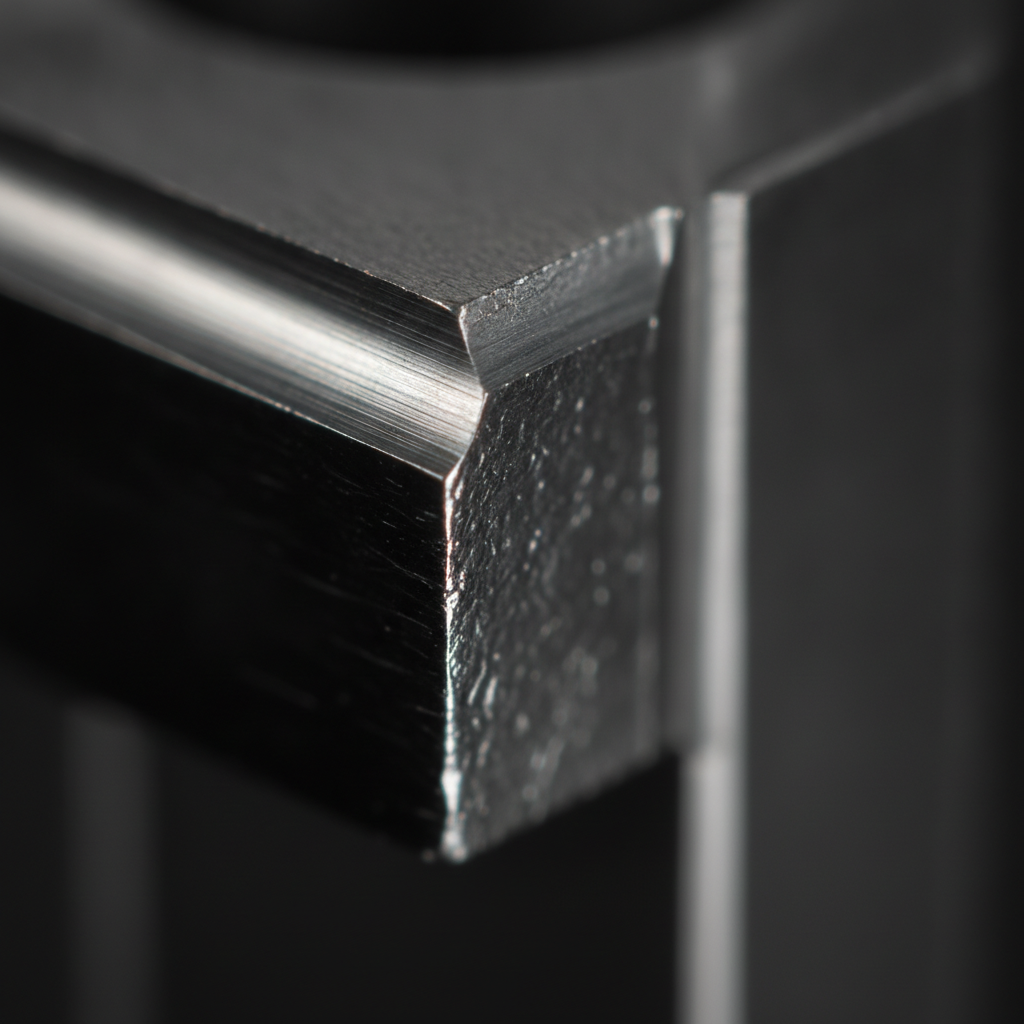
DLC (diamond-like carbon) is a metastable carbon film containing sp3 and sp2 bonds that delivers high hardness, low friction, and chemical inertness. It’s deposited in vacuum by sputtering, PACVD, or filtered arc. The coating’s structure and interlayers are tuned to the substrate to maximize adhesion and performance.
DLC is engineered carbon, not gemstones. It forms at low thickness (commonly 1–4 μm) and adheres through carefully managed surface activation and metallic interlayers (e.g., Cr, Ti). The film’s low shear and high hardness reduce scuffing, galling, and adhesive wear on steels and carbides without changing part geometry.
- Typical properties: microhardness ~1,800–3,000 HV; friction against steel ~0.05–0.15; electrical resistivity high; chemical inertness good.
- Thermal envelope: many tool steels retain temper up to ~250–300 °F during processing; carbides tolerate higher, but control remains crucial.
- Coating families: hydrogenated (a-C:H), metal-doped (Me-DLC), and hydrogen-free ta-C, each balancing stress, adhesion, and durability.
For a deeper service perspective, see our internal explainer on DLC coating services and how we tailor recipes to production realities.
What DLC is not
- It’s not gemstone grading; consumer diamond certification resources exist but are unrelated to engineered DLC films (e.g., general diamond certification overviews).
- It’s not paint or epoxy; architectural coating pages show different chemistries and cure paths (for contrast, see an unrelated automatic coating portfolio).
- It’s different from automotive ceramic topcoats; consumer guides discuss PPF/ceramic stacks, not vacuum carbon films (e.g., an unrelated ceramic-over-PPF article).
Why DLC matters for manufacturers in Woodbridge
DLC cuts friction and combats adhesive wear in stamping, plastics, and cutting, reducing downtime and scrap. In Woodbridge and the Regional Municipality of York, local support at 110 Sharer Rd lets teams iterate fast—from prototype trials to stable, ISO-documented production runs.
In our experience supporting automotive and tooling clusters near Woodbridge, the fastest savings come from stabilizing first-off quality. Lower friction means cooler tools, steadier part ejection, and less material pickup, which together push longer intervals between interventions.
- Stamping: DLC lowers galling on AHSS and aluminum blanks, often delivering 2–4× interval extensions when surfaces are pre-polished and aligned to Ra 0.02–0.05 μm.
- Plastics: On injection molds, DLC reduces sticking and burnish; ejector pins and slides release cleaner, improving dimensional consistency on multi-cavity tools.
- Cutting: For non-ferrous machining, DLC-coated carbide inserts maintain sharpness, with edge integrity visible after multi-shift runs.
- Components: Precision shafts, plungers, and valve parts show smoother start-up and less break-in time under boundary lubrication.
For a complete primer on vacuum deposition, browse our PVD coating guide covering mechanisms and application fit.
The DLC coating process (step-by-step)
A production-grade dlc coating process follows a closed-loop sequence: receipt and inspection; cleaning and masking; surface activation; interlayer deposition; carbon growth; controlled cool-down; post-lap; and final QA. Each stage has numeric targets for roughness, temperature, and film thickness that lock in repeatability.
Workflow you can run this week
- Incoming QC: Verify drawing rev, alloy, heat treatment, and hardness. Capture baseline roughness (e.g., Ra ≤ 0.05 μm for sealing/ejection surfaces). Photograph critical edges.
- Degrease and ultrasonic clean: Use sequential alkaline and solvent stages; DI rinse to conductivity targets; dry in filtered air. Aim for zero visible residues under UV.
- Media preparation: Sandblast or microblast only masked regions if required for grip; keep functional areas protected. Track media lot and pressure (e.g., 2–4 bar for microblast).
- Masking: Protect sharp edges, threads, and critical fits. Log all masks by cavity and feature to reproduce on re-coats.
- Pre-polish / lap: Bring contact surfaces to Ra 0.02–0.05 μm; clean lint-free. Smooth surfaces reduce stress concentrators and aid uniform nucleation.
- Fixture: Use balanced, shadow-free racks; avoid line-of-sight occlusion. Record clocking and spacing so paired tools ride in the same zones each batch.
- Vacuum pump-down: Evacuate to process base pressure (e.g., 1–5×10⁻³ mbar). Heat soak parts uniformly; document thermocouple profiles.
- Surface activation: Argon or mixed-gas plasma clean; monitor bias current and time to achieve repeatable sputter-etch depth.
- Interlayer(s): Deposit Ti, Cr, or CrN seed for adhesion; measure thickness (e.g., 0.2–0.6 μm) by quartz crystal microbalance or coupon metrology.
- Carbon growth: Run DLC recipe (sputter, PACVD, or filtered arc) to target thickness 1–4 μm. Manage compressive stress by bias pulsing and temperature.
- Cool-down and vent: Ramp down power; avoid fast venting that can shock thin edges. Handle with nitrile gloves; bag immediately.
- Post-lap / polish: Lightly lap to restore mirror finish and hit Ra targets; clean; then perform final thickness, adhesion, and coverage checks.
We document each run under ISO 9001:2015 and Nuclear N299.3 controls, so process windows and metrology trail each batch. For context on deposition families, skim our overview of PVD types.
Methods and variants: choosing the right approach
Choose method by substrate, geometry, and finish: sputtered PVD for lower stress and tight thickness control; PACVD for conformal coverage on complex parts; filtered arc for dense, hydrogen-free films. Match interlayers and temperature to the alloy’s heat history.
| Method | When to use | Typical film | Notes |
|---|---|---|---|
| PVD sputter (a-C:H / Me-DLC) | Carbide and tool steel with tight flatness; sharp-feature tooling | 1–3 μm, lower stress | Uniform thickness; excellent for flat dies and inserts |
| PACVD (a-C:H) | Complex 3D components, internal features, ejector pins | 1–4 μm, very conformal | Great coverage; mind hydrogen content vs. application |
| Filtered cathodic arc (ta-C) | Extreme wear, very low friction needs on robust substrates | 0.5–2 μm, very dense | High intrinsic stress; needs careful stress management |
If you’re weighing surface families beyond DLC, our types of PVD primer compares hardness, friction, and heat budgets across common recipes.
Materials and design rules for DLC success
DLC performs best on fine-polished tool steels, carbides, nitrided steels, and select stainless grades. Keep contact surfaces smooth (Ra 0.02–0.05 μm), avoid undercuts that shadow line-of-sight, and mask sharp edges. Control substrate heat history to protect hardness.
- Substrates: H13, D2, M2, 420/440C stainless (with care), tungsten carbide, nitrided 4140/4340. Verify heat treat and temper window.
- Prep detail: Deburr thoroughly; break razor edges minimally to preserve geometry; mirror-polish sealing and ejection zones.
- Geometry: Maintain line-of-sight; consider relief angles; design fixtures to rotate or oscillate for deep features.
- Masking: Plug threads and precision fits; define datum references so masks repeat on re-coats.
- Thermal budget: Keep process below tempering thresholds; log dwell times; re-verify hardness post-process when critical.
For program-level planning, our PVD methods overview outlines how fixturing and rotation strategies reduce shadowing on complex parts.
Quality, inspection, and certification
Production DLC needs documented thickness, adhesion, and roughness, plus traceable recipes under ISO 9001:2015. In regulated sectors, N299.3 vendor approval strengthens QA evidence. Use repeatable metrology and lot histories to stabilize future re-coats.
- Thickness: Target 1–4 μm via calo test, ball-crater, or XRF on coupons; correlate readings across chambers.
- Adhesion: Record scratch test critical loads and failure modes; maintain witness coupons per batch.
- Roughness: Verify Ra on functional zones (e.g., ≤ 0.05 μm) pre- and post-lap; correlate to part performance.
- Coverage: Use borescope or microscopy on complex geometries; photo-document hard-to-see areas for re-coat guidance.
- Traceability: Link lot, fixture position, and recipe version; archive ramp/soak curves and pressure histories.
Sputtek operates as an ISO 9001:2015 and Nuclear N299.3 approved vendor. That means every run ties to controlled procedures, training matrices, and retained records that speed audits and customer qualifications.
Best practices and checklists
Win with clean prep, consistent fixturing, and disciplined post-processing. Standardize roughness and masking, run paired tooling together, and validate with fast metrology loops. Small controls produce large gains in coating life and process uptime.
Coating readiness checklist
- Confirm alloy, hardness, and heat-treat certs on receipt.
- Polish to Ra 0.02–0.05 μm for functional zones; deburr all edges.
- Define masking plan with datums; bag masks for re-use.
- Establish fixture symmetry and distances; photograph loadout.
- Set acceptance ranges: thickness, adhesion loads, and Ra.
Troubleshooting quick hits
- Poor adhesion: Recheck cleaning and activation; adjust interlayer thickness; reduce stress with bias pulsing.
- High friction: Verify post-lap; target smoother Ra; consider ta-C or metal-doped variants for your media pair.
- Edge chipping: Gentle cooling and slower vent; round razor edges; review fixture shading.
- Non-uniform thickness: Balance load, add rotation/planetary motion, or switch to PACVD for deep features.
Tools, systems, and fixturing
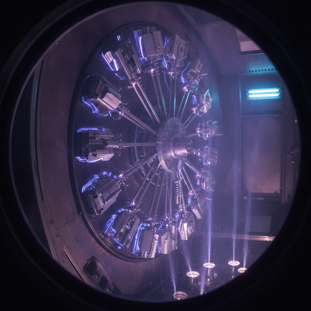
Throughput depends on chamber capacity, carousel design, heating uniformity, and recipe control. Sputtek’s SPUN 2,000 and SPUN 4,000 PVD systems enable large, consistent DLC batches, supported by in-house sandblasting, microblasting, lapping, and a QC lab for rapid feedback.
- Capacity planning: High-capacity systems (up to multi-thousand kg per cycle) stabilize takt time for large programs.
- Fixturing: Balanced, shadow-minimized racks reduce rejects and improve repeatability; rotation improves coverage.
- Support services: In-house cleaning, stripping, and post-lap compress lead times and reduce handling risk.
- R&D agility: Engineering-led recipes and test coupons shorten time-to-stable production settings.
For a broad look at deposition system families, see our PVD coating guide and related primers on PVD types and PVD methods.
Request a 20-minute DLC process review
- Map your substrate, geometry, and temperature window
- Validate roughness, interlayer, and masking targets
- Plan fixturing and batch flow matched to your takt time
We’re at 110 Sharer Rd in Woodbridge—drop off prototypes and we’ll return a documented recommendation you can scale.
Case studies and examples
Across stamping, plastics, machining, and components, DLC reduces friction-driven failures and extends intervals. The biggest gains come when parts are polished, masked, and fixtured consistently, and when paired tools run together in the same cycle.
Stamping dies (automotive AHSS and aluminum)
- Challenge: Galling and pickup on draw beads and trim edges after short runs.
- Action: Ra polished to ~0.03 μm; Cr/CrN adhesion layer; a-C:H DLC at ~2 μm; matched beads fixtured adjacently.
- Result: More stable draw, cleaner trims, and extended maintenance intervals reported on similar tool sets.
Plastic injection tooling
- Challenge: Sticking in multi-cavity molds; difficult ejection and scuffing.
- Action: DLC on ejector pins, slides, and lifters; tight masking on shut-offs; post-lap to restore mirror finish.
- Result: Smoother ejection, less burnish, steadier part dimensions over long cycles.
Non-ferrous machining
- Challenge: Built-up edge on aluminum cutting; rapid edge wear on carbide inserts.
- Action: DLC on polished rake and flank; lower-stress sputter variant ~1.5–2 μm; controlled cool-down; post-lap.
- Result: Edge integrity maintained through multi-shift runs; reduced built-up edge and smoother finishes.
Precision components (medical, pharma, packaging)
- Challenge: Start-up scuffing and break-in wear on sliding components under boundary lubrication.
- Action: DLC on plungers and shafts; fine polish; strict clean handling; adhesion verified with coupon scratch tests.
- Result: Lower start-up torque feel and improved surface stability during validation testing.
Frequently Asked Questions
These quick answers help engineers choose and apply DLC faster. Each response is concise and designed for voice or chat extraction so your team can move forward without guesswork.
What thickness should I target for DLC?
Most production parts run 1–4 μm. Thin edges or sharp features often prefer 1–2 μm to limit stress. Flat dies and inserts commonly sit near 2 μm. Verify with calo or XRF on coupons and correlate to part life.
Can DLC handle high heat?
DLC excels in boundary lubrication and moderate temperatures. Many tool steels maintain temper below roughly 250–300 °F during processing. Carbide can handle more, but always confirm the heat history and hardness after coating if critical.
Which method is best: sputter, PACVD, or filtered arc?
Match method to geometry and stress. Sputter offers uniform, lower-stress films for flat dies. PACVD gives superior conformity on complex parts. Filtered arc yields dense ta-C but with higher intrinsic stress requiring careful management.
How smooth should surfaces be before coating?
Aim for Ra 0.02–0.05 μm on functional zones. Polish and deburr to remove stress risers. After coating, a light lap restores mirror finish and ensures the low friction benefit shows up in production.
Key takeaways and next steps
Treat DLC as a controlled production process, not a black box. Define roughness, interlayer, and thickness targets up front, then run consistent fixtures and validate with quick metrology. Local, ISO-backed support makes iteration fast and reliable.
- Use a documented dlc coating process from incoming QC through final inspection.
- Lock in adhesion with clean prep, correct interlayers, and temperature control.
- Polish to tight Ra and post-lap to unlock the friction advantage.
- Choose method (sputter, PACVD, filtered arc) by geometry and stress tolerance.
- Leverage local support at 110 Sharer Rd in Woodbridge for rapid trials and re-coats.
Ready to stabilize a program? Bring sample parts to our Woodbridge facility. We’ll map substrate, geometry, and fixturing options—and return a step-by-step plan you can scale on your timeline.
Explore more on deposition
If you’re evaluating surface technologies beyond DLC, review foundational PVD resources to compare friction, hardness, and temperature envelopes. These primers help you select the right coating for each tool or component.
To round out your research, see our practical guides on PVD coatings, compare PVD types, and dig into PVD methods. When you’re ready to execute, our DLC services primer shows how we translate specs into production.


