Types of physical vapor deposition are the distinct vacuum processes—sputtering, evaporation, cathodic arc, ion plating, HiPIMS, and IBAD—used to form thin, hard films on parts. From our Woodbridge facility at 110 Sharer Rd, we apply these PVD types to extend tool life, cut friction, and boost reliability on production tooling and precision components.
By Ron — Sputtek • Last updated: 2026-06-06
Summary
This guide explains what PVD is, how it works, and when to choose each PVD type for best performance. You’ll see quick comparisons, best practices, and real examples from stamping, machining, molding, and medical and energy parts—so you can match the right coating method to your substrate, geometry, and operating limits.
- Understand how sputtering, evaporation, arc, ion plating, HiPIMS, and IBAD differ.
- See which PVD method fits steels, stainless, carbide, aluminum, and complex shapes.
- Use checklists for prep, fixturing, masking, and post-polish (lapping) success.
- Review a side-by-side comparison of adhesion, density, roughness, and heat input.
- Learn how Sputtek’s in-house processes and SPUN systems scale from prototype to volume.
What is physical vapor deposition (PVD)?
Physical vapor deposition is a family of vacuum-coating processes that vaporize source material and condense it as a thin, hard film on parts. PVD films are typically 1–5 microns thick, deposited at ~390–930°F (200–500°C), and engineered to improve wear, friction, and corrosion performance without changing part dimensions.
PVD refers to vacuum-based techniques that generate energetic atoms, ions, or droplets from a solid source and drive them toward a substrate to form a functional coating. Common films include TiN, TiCN, AlTiN, CrN, and DLC, each tuned for hardness, lubricity, or heat resistance.
- Vacuum environment: Base pressures often reach 10−5 to 10−6 Torr to minimize contamination and ensure dense films.
- Line-of-sight dynamics: Many PVD types are directional; fixturing and rotation help achieve uniform coverage on complex geometries.
- Thickness control: Typical builds are 1–5 μm; multi-layer stacks and gradients are used for advanced stress management and performance.
- Adhesion mechanisms: Ion bombardment (etch) and reactive chemistry improve nucleation and bond strength at the interface.
In our experience, the fastest way to boost tool life is to pair the right PVD chemistry with the right process physics—then lock it in with disciplined prep, fixturing, and QC.
Why the types of physical vapor deposition matter
Selecting the correct PVD type aligns process physics with your part’s substrate, geometry, and temperature limits. For manufacturers in Woodbridge and the Regional Municipality of York, this choice directly impacts uptime, scrap rates, and regulatory compliance on production tooling and components.
Each PVD method has distinct energy input, plasma density, angular distribution, and thermal load. Those traits determine coating density, residual stress, adhesion, and roughness—core properties that show up as real outcomes: fewer tool changes, cleaner edges, and more stable dimensions over long runs.
- Substrate compatibility: Hardened steels and carbides favor higher-energy approaches; heat‑sensitive alloys may need gentler processes.
- Geometry fit: Deep cavities and threads challenge line‑of‑sight processes; ion assistance and rotation strategies mitigate shadowing.
- Throughput vs. quality: Higher rates can raise roughness or stress; recipe tuning balances speed and film integrity.
- Compliance: Documented prep, parameter control, and testing support ISO 9001:2015 and Nuclear N299.3 quality requirements.
Local considerations for Woodbridge
- Plan drop-offs and pickups around the SmartCentres Woodbridge area to streamline logistics for batch turns and trials.
- Account for winter humidity swings to keep incoming parts clean and dry before vacuum load-in.
- Schedule deliveries to avoid rush near the Weston Rd / Highway 7 corridor; we coordinate dock times to protect surface finish integrity.
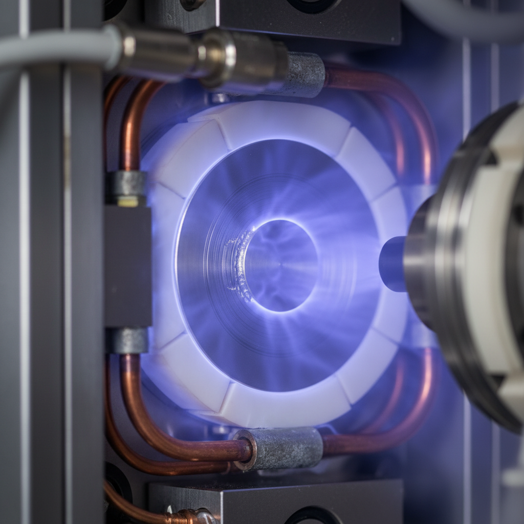
How physical vapor deposition works
PVD works by preparing the surface, evacuating to high vacuum, energizing a source (target) to release atoms or ions, and condensing that vapor as a dense film on rotating, fixtured parts. In‑process bias and reactive gases control adhesion, composition, and microstructure for target performance.
- Preparation: Degreasing, ultrasonic cleaning, and in‑house sandblasting/microblasting remove oils and oxides.
- Load & pumpdown: Parts are fixtured and loaded; pumps reach 10−5–10−6 Torr base pressures.
- Heat & ion etch: Substrates are brought to temperature; argon ion bombardment cleans and activates the surface.
- Deposition: Sputtering, evaporation, or arc releases source material; reactive gases (e.g., N2, C2H2) form nitrides/carbides.
- Rotation & bias: Part holders rotate; substrate bias shapes energy and density for adhesion and stress control.
- Cool & inspect: Controlled cool‑down; QC verifies thickness, adhesion (tape/scribe), and roughness (Ra/Rz) before release.
| Stage | Key controls | Typical metrics |
|---|---|---|
| Prep | Cleanliness, roughness, masking | Ra pre‑spec (e.g., ≤0.05–0.2 μm for cutting tools) |
| Pumpdown | Base pressure, leak rate | 10−5–10−6 Torr base |
| Etch | Bias voltage/current, Ar flow | Improved adhesion; clean interface |
| Deposition | Power density, gas ratio, temperature | 1–5 μm thickness; uniformity per spec |
| QC | Thickness, adhesion, roughness | Documented pass/fail vs. recipe |
We’ve found that disciplined preparation and fixturing eliminate most coating issues before they start—saving debug time on the back end.
Types of physical vapor deposition (PVD)
The main PVD types are magnetron sputtering (DC/RF), reactive sputtering, high‑power impulse magnetron sputtering (HiPIMS), cathodic arc (with filtered variants), thermal evaporation (resistive/e‑beam), ion plating, and ion‑beam assisted deposition (IBAD). Each balances density, roughness, heat input, and conformality differently.
Below we profile each method, highlight where it excels, and note trade‑offs that matter on the plant floor. Use these as practical guardrails when choosing a process for your substrate and geometry.
Magnetron sputtering (DC/RF)
- How it works: Ions knock atoms from a solid target; magnets trap electrons to boost plasma density and rate.
- Strengths: Smooth films, good thickness control, excellent for metals/nitrides on tools, molds, and components.
- Watch‑outs: Directional (line‑of‑sight); plan fixturing and rotation for cavities and edges.
- Typical uses: TiN/TiCN/CrN on stamping dies and wear inserts; AlTiN on carbide end mills for hot hardness.
Reactive sputtering
- How it works: Metallic target sputtered in reactive gas (e.g., N2 or C2H2) to form nitrides/carbides in‑flight/on‑surface.
- Strengths: Tight composition control; wide material palette; proven uniformity for production runs.
- Watch‑outs: Target “poisoning” reduces rate; requires closed‑loop gas/power recipes for stability.
- Typical uses: CrN on aluminum die cast tooling for corrosion/galling control; TiCN for stamping dies.
HiPIMS (high‑power impulse magnetron sputtering)
- How it works: Short, intense power pulses create highly ionized metal flux for dense, adherent films.
- Strengths: Arc‑like density with sputter‑level smoothness; better step coverage than conventional sputtering.
- Watch‑outs: Lower average rate; recipe tuning is critical for stress control and throughput.
- Typical uses: AlTiN/AlCrN for high‑speed machining where heat and crater wear dominate.
Cathodic arc evaporation
- How it works: Localized cathode spots vaporize metal; highly energetic ions travel to the substrate.
- Strengths: Very dense, well‑adhered films; high deposition rates for TiN, TiCN, AlTiN.
- Watch‑outs: Droplets (macroparticles) can raise roughness; filtered arc variants reduce them.
- Typical uses: Heavy‑duty stamping and forming dies; erosion‑resistant edges on hard tooling.
Filtered cathodic arc (FCVA)
- How it works: Magnetic filters remove droplets from arc plasma to yield smoother films.
- Strengths: Arc‑level adhesion with improved roughness—valuable for low‑Ra requirements.
- Watch‑outs: Added complexity and hardware; may limit rate compared with unfiltered arc.
- Typical uses: DLC and decorative‑functional stacks where smoothness and adhesion both matter.
Thermal evaporation (resistive and e‑beam)
- How it works: Heat or an electron beam vaporizes material; atoms condense on the part.
- Strengths: Gentle energy input; good for heat‑sensitive substrates and certain metals.
- Watch‑outs: More directional; step coverage can be limited without ion assist.
- Typical uses: Barrier and decorative layers; niche functional stacks where low thermal load is key.
Ion plating
- How it works: Evaporated atoms are simultaneously bombarded with ions; substrate is biased.
- Strengths: Improved adhesion and density over pure evaporation; good for complex shapes.
- Watch‑outs: Balancing bias to avoid overheating thin edges and small features.
- Typical uses: Precision components and molds needing smoother surfaces than arc can provide.
IBAD (ion‑beam assisted deposition)
- How it works: A directed ion beam assists condensation to tailor film density, stress, and texture.
- Strengths: Excellent control over microstructure; helps with adhesion on challenging substrates.
- Watch‑outs: Specialized equipment; slower throughput than mainstream sputter/arc options.
- Typical uses: High‑value components where precision film properties outweigh cycle time.
When we assess new parts, we weigh rate, roughness, density, and geometry coverage in that order—then model expected wear modes to choose between sputter, arc, or hybrid ion‑assisted paths.
Comparison: which PVD method fits your part?
Match method to need: sputtering for smooth control, HiPIMS for dense smooth films, arc for speed and adhesion, filtered arc for smoother DLC, evaporation/ion plating for low heat, and IBAD for precision tailoring. Use the table to balance density, roughness, heat input, and geometry coverage.
| Method | Density | Surface roughness | Heat input | Rate | Geometry coverage | Common films |
|---|---|---|---|---|---|---|
| Magnetron sputter | High | Low (smooth) | Moderate | Moderate | Directional; rotation helps | TiN, TiCN, CrN, AlTiN |
| Reactive sputter | High | Low | Moderate | Moderate | Directional | CrN, TiCN, DLC stacks |
| HiPIMS | Very high | Low | Moderate | Lower avg | Better step coverage | AlTiN, AlCrN |
| Cathodic arc | Very high | Higher (droplets) | Higher | High | Good; ionized flux | TiN, TiCN, AlTiN |
| Filtered arc | Very high | Lower than arc | Higher | Moderate | Good | DLC, smooth TiN |
| Evaporation | Medium | Low | Low | High (some metals) | Line‑of‑sight | Decorative/functional metals |
| Ion plating | High | Low | Moderate | Moderate | Improved vs evap | Metals, nitrides |
| IBAD | High (tunable) | Low | Low–moderate | Lower | Excellent control | Precision stacks |
If you’re unsure, start with sputtering for smooth control and move up the energy ladder (HiPIMS, arc) as needed for density and adhesion while watching roughness and thermal budget.
Best practices for PVD success
Get repeatable performance by locking in surface finish, heat treatment, and fixturing before coating. Document prep, use ion etch with the right bias, validate recipes on coupons, and finish with controlled lapping when Ra targets demand it.
- Design for coating: Ease sharp corners where permissible; add handling features to avoid touch points.
- Surface finish: For cutting tools, target pre‑Ra in the 0.05–0.2 μm range; for molds, match demolding goals.
- Heat treatment: Stabilize microstructure before coating; confirm tempering won’t shift at deposition temperatures.
- Fixturing: Maximize line‑of‑sight and rotation; mask precision bores and threads to maintain fits.
- Ion cleaning: Bias‑assisted argon etch promotes adhesion by removing last‑mile oxides and contaminants.
- Recipe validation: Pilot on coupons or non‑critical features; lock parameters and measurement methods.
- Post‑polish: Lapping can reduce friction and break in a film without sacrificing thickness where smoothness is critical.
Need a second opinion? Our engineering team at 110 Sharer Rd can review substrate, geometry, and duty cycle, then recommend a PVD stack and process flow that fits your line speed and QA rules.
Tools and resources we use
We run high‑capacity SPUN PVD systems (2,000 and 4,000 series) and provide end‑to‑end in‑house prep and QC. That lets us scale from prototypes to large, repeatable batches while keeping adhesion, roughness, and thickness inside tight production windows.
- SPUN 2,000: High‑capacity system for consistent large‑batch runs and multi‑layer recipes.
- SPUN 4,000: Expanded capacity for heavier fixtures and complex part families.
- Custom system design: We design PVD solutions for unique throughput, geometry, and material needs.
- In‑house processes: Sandblasting, microblasting, degreasing, stripping, polishing, after‑coating lapping, and QC laboratory testing.
- DLC expertise: For ultra‑low friction and chemically inert surfaces, see our complete DLC coating guide.
Material behavior and surface chemistry often interact with polymer tooling and release dynamics; for background on polymer structure effects, this primer on polymer structure for custom applications provides useful context for molding environments.
Case studies and real‑world examples
Here are concise, field‑tested examples that show how matching PVD type to duty cycle and substrate translates into measurable gains—longer tool life, lower scrap, and steadier quality in production.
- Stamping dies (TiCN on tool steel): Galling reduced and edge retention stabilized across long progressive runs.
- Carbide end mills (AlTiN via sputter/HiPIMS): Better hot hardness and crater wear resistance at high SFM.
- Injection molds (DLC/CrN stacks): Improved demolding and surface integrity on sticky polymers.
- Aluminum die cast tooling (CrN): Corrosion and soldering resistance extended maintenance intervals.
- Medical components (TiN): Biocompatible finish with controlled roughness for mating precision.
- Pharma punches (DLC): Lower sticking and cleaner edges supported tighter weight variation control.
For a broad sense of how surface technologies are deployed across industries, see this industrial coatings portfolio showing varied applications of finishing methods.
FAQ: types of physical vapor deposition
These quick answers address common, high‑stakes questions manufacturing teams ask when choosing between sputtering, evaporation, arc, ion plating, HiPIMS, and IBAD for production tooling and precision components.
How do I choose the right PVD method for my part?
Start with the failure mode and substrate. If you need smooth surfaces and tight control, pick sputtering or HiPIMS. For maximum adhesion and speed, consider arc or filtered arc. If heat is a constraint, look at evaporation or ion plating. Confirm with a trial on coupons before a full batch.
How thick should a PVD coating be?
Most functional PVD films land between 1 and 5 microns. Complex stacks or extreme wear cases may justify thicker builds. More thickness isn’t always better—excess can add stress or affect fits. Align thickness to duty cycle and dimensional limits, then verify with cross‑section or XRF where applicable.
Can aluminum parts be PVD coated?
Yes. Aluminum and its alloys can be coated, but they require tailored prep, adhesion layers, and careful heat input. CrN and certain DLC stacks are common choices. Mask critical dimensions, and validate demolding or corrosion resistance targets in your actual production environment.
How does PVD compare to thermal spray or HVOF?
PVD builds thin, dense films (microns) for precision surfaces and tight tolerances. Thermal spray/HVOF applies thicker coatings (tens to hundreds of microns) for erosion and impact resistance. Use PVD for low‑friction, wear control on precision features; use thermal spray where thickness and impact toughness dominate.
Key takeaways
Choose the PVD type that aligns with substrate, geometry, and failure mode; lock in prep and fixturing; and validate with small trials. That’s how you turn lab‑grade coatings into stable, high‑yield production performance.
- Sputtering and HiPIMS deliver smooth, controllable films; arc maximizes adhesion and rate; filtered arc smooths DLC.
- Confirm thermal limits before selecting higher‑energy methods or longer cycles.
- Prep quality, fixturing access, and masking discipline drive coating uniformity and feature protection.
- Target 1–5 μm thickness and verify with consistent, documented QC checks.
Next steps
Share your substrate, geometry, and wear history with our team, and we’ll recommend a PVD method, chemistry, and process window. We support prototype trials and scale to stable, high‑volume batches with documented QC.
Have a part that keeps failing on the same edge or cavity? Bring specimen photos and your duty cycle notes to our Woodbridge facility at 110 Sharer Rd. We’ll map the wear mode to a coating stack and process flow and coordinate logistics around the Weston Rd / Highway 7 corridor for efficient turns.
For background reading on material interactions that can influence release and surface energy, see this overview of thermoplastic vs. thermosetting polymers, and this explainer on when to use GPC analysis during materials development.


